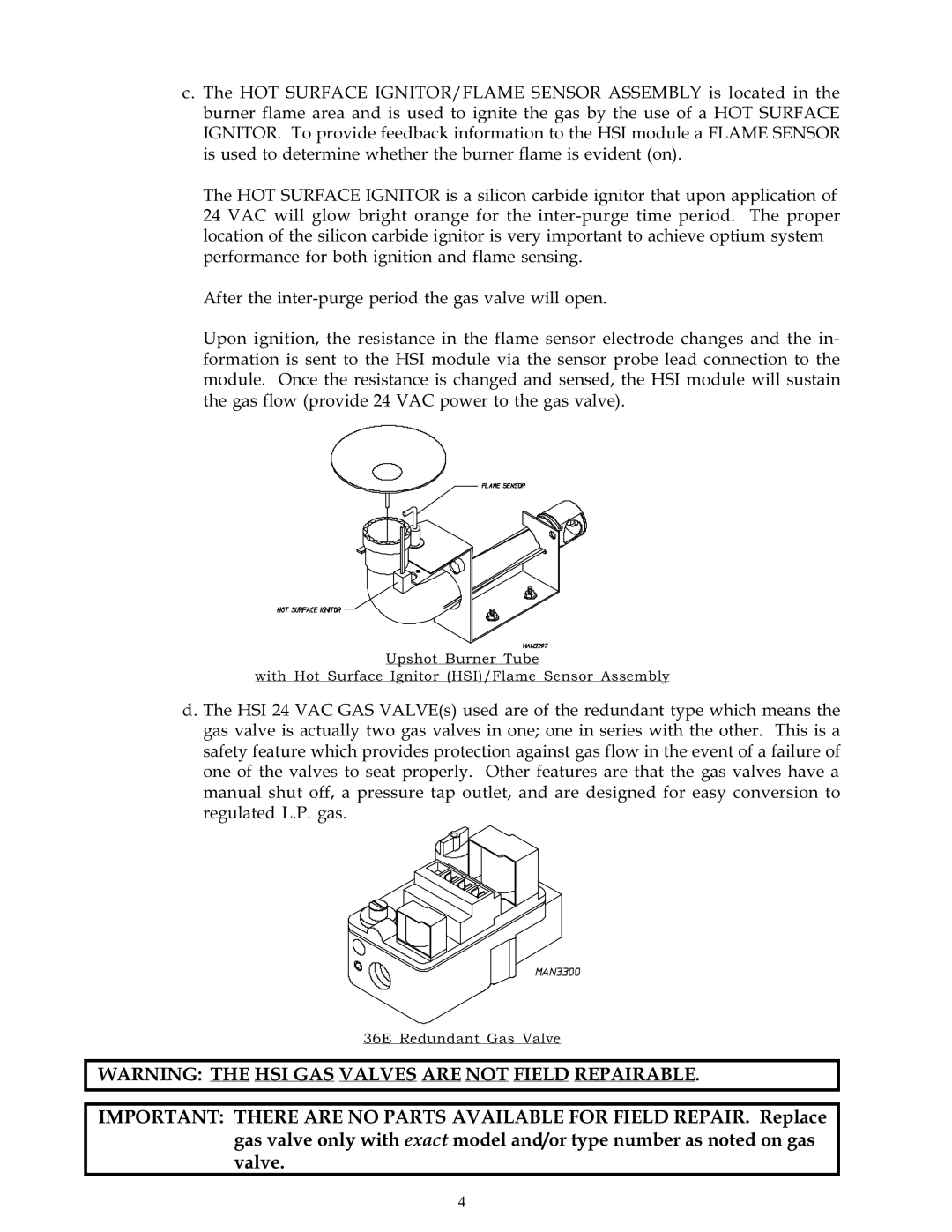
c. The HOT SURFACE IGNITOR/FLAME SENSOR ASSEMBLY is located in the burner flame area and is used to ignite the gas by the use of a HOT SURFACE IGNITOR. To provide feedback information to the HSI module a FLAME SENSOR is used to determine whether the burner flame is evident (on).
The HOT SURFACE IGNITOR is a silicon carbide ignitor that upon application of 24 VAC will glow bright orange for the
After the
Upon ignition, the resistance in the flame sensor electrode changes and the in- formation is sent to the HSI module via the sensor probe lead connection to the module. Once the resistance is changed and sensed, the HSI module will sustain the gas flow (provide 24 VAC power to the gas valve).
Upshot Burner Tube
with Hot Surface Ignitor (HSI)/Flame Sensor Assembly
d. The HSI 24 VAC GAS VALVE(s) used are of the redundant type which means the gas valve is actually two gas valves in one; one in series with the other. This is a safety feature which provides protection against gas flow in the event of a failure of one of the valves to seat properly. Other features are that the gas valves have a manual shut off, a pressure tap outlet, and are designed for easy conversion to regulated L.P. gas.
36E Redundant Gas Valve
WARNING: THE HSI GAS VALVES ARE NOT FIELD REPAIRABLE.
IMPORTANT: THERE ARE NO PARTS AVAILABLE FOR FIELD REPAIR. Replace gas valve only with exact model and/or type number as noted on gas valve.
4