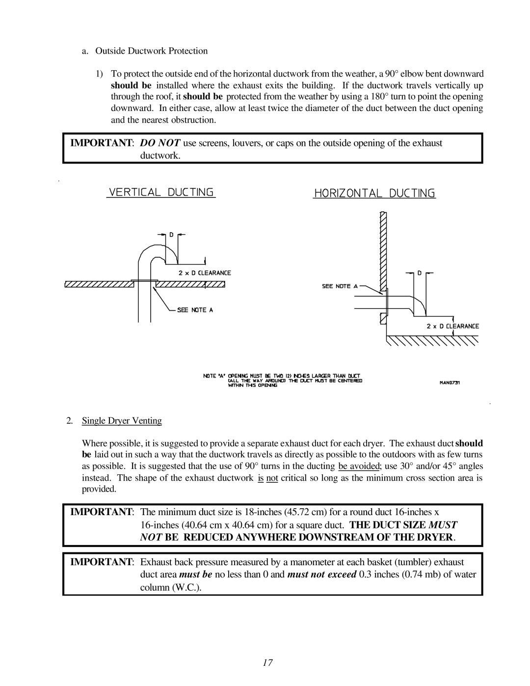
a.Outside Ductwork Protection
1)To protect the outside end of the horizontal ductwork from the weather, a 90° elbow bent downward should be installed where the exhaust exits the building. If the ductwork travels vertically up through the roof, it should be protected from the weather by using a 180° turn to point the opening downward. In either case, allow at least twice the diameter of the duct between the duct opening and the nearest obstruction.
IMPORTANT: DO NOT use screens, louvers, or caps on the outside opening of the exhaust ductwork.
2.Single Dryer Venting
Where possible, it is suggested to provide a separate exhaust duct for each dryer. The exhaust duct should be laid out in such a way that the ductwork travels as directly as possible to the outdoors with as few turns as possible. It is suggested that the use of 90° turns in the ducting be avoided; use 30° and/or 45° angles instead. The shape of the exhaust ductwork is not critical so long as the minimum cross section area is provided.
IMPORTANT: The minimum duct size is
IMPORTANT: Exhaust back pressure measured by a manometer at each basket (tumbler) exhaust duct area must be no less than 0 and must not exceed 0.3 inches (0.74 mb) of water column (W.C.).
17
