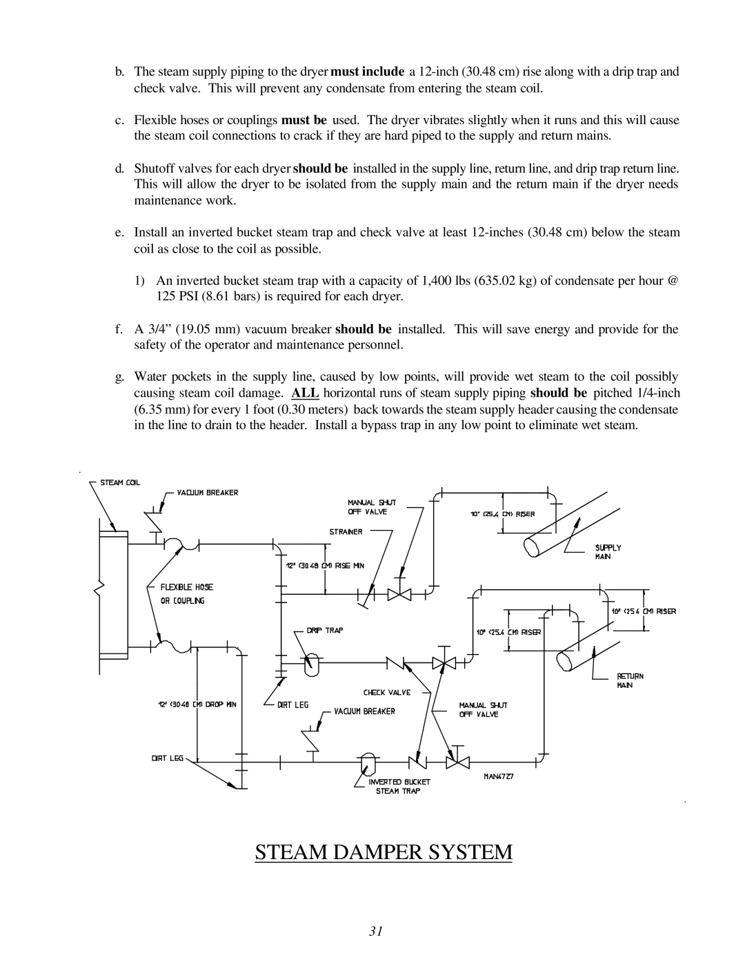
b.The steam supply piping to the dryer must include a
c.Flexible hoses or couplings must be used. The dryer vibrates slightly when it runs and this will cause the steam coil connections to crack if they are hard piped to the supply and return mains.
d.Shutoff valves for each dryer should be This will allow the dryer to be isolated maintenance work.
installed in the supply line, return line, and drip trap return line. from the supply main and the return main if the dryer needs
e.Install an inverted bucket steam trap and check valve at least
1)An inverted bucket steam trap with a capacity of 1,400 lbs (635.02 kg) of condensate per hour @ 125 PSI (8.61 bars) is required for each dryer.
f.A 3/4” (19.05 mm) vacuum breaker should be installed. This will save energy and provide for the safety of the operator and maintenance personnel.
g.Water pockets in the supply line, caused by low points, will provide wet steam to the coil possibly causing steam coil damage. ALL horizontal runs of steam supply piping should be pitched
STEAM DAMPER SYSTEM
31