Polaris Residential Gas Water Heater
Installation Instructions and Use & Care Guide
Table of Contents
Your safety and the safety of others are very important
Important Instructions
Page
Installer and Owner Responsibilities
INSTALLATION INSTRUCTIONS
Excessive Weight Hazard
Unpacking the Water Heater
FIRE AND EXPLOSION HAZARD
Location Requirements
Site Location
Figure 1 Garage Installation
Condensate Trap Assembly
Clearances and Accessibility
CONDENSATE LINE
Figure 3A 2” Condensation Trap Installation
Venting
Follow all instructions to locate and install the vent pipe system
Condensate Drain Line
Carbon Monoxide Hazard
Vent Pipe Material
Vent Pipe Installation
Vent Pipe Length
Figure 5 Correct and Incorrect Pipe Fittings
US Installations
Vent Termination Locations
Canadian Installations
Figure 6 Minimum Clearances for Inlet/Outlet and Concentric Vent
Standard Horizontal Termination
INLET/OUTLET VENT TERMINATIONS 100,000 - 150,000 BTU/HR
Alternative Horizontal Termination
Figure 8A Alternate Horizontal Termination
Figure 9A Vertical Termination 100,000 - 150,000 BTU/Hr Models
VERTICAL TERMINATIONS 100,000 - 150,000 BTU/HR
Venting Additional Polaris Units 100,000 - 150,000 BTU/hr Models
Figure 10A 2 Inch Concentric Vent
CONCENTRIC VENT TERMINATIONS 100,000 - 150,000 BTU/HR
Figure 11A Through the Wall Termination
Figure 12A Through the Roof Termination
Standard Horizontal Termination
INLET/OUTLET VENT TERMINATIONS 175,000+ BTU/HR
Alternative Horizontal Termination
Figure 7B Standard Horizontal Termination 175,000+ BTU/Hr models
Figure 9B Vertical Termination 175,000+ BTU/Hr models
VERTICAL TERMINATIONS 175,000+ BTU/HR
Venting Additional Polaris Units 175,000+ BTU/Hr Models
Concentric Venting Multiple Water Heaters All Models
CONCENTRIC VENT TERMINATIONS 175,000 + BTU/HR
Figure 13B Concentric Vent Piping Installation
Figure 10B 3 Inch Concentric Vent
WATER PIPING SYSTEM
Piping Installation
Gas Input Rate
Corrosion and Water Quality
General Information
Tempering Valve Installation
Closed System/Thermal Expansion
Combination Space Heating/Potable Water System
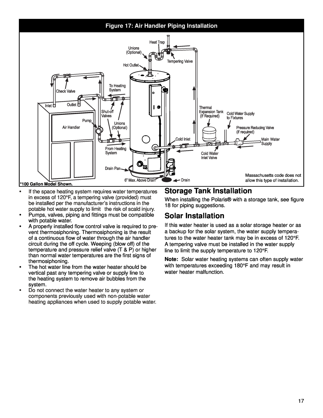
Figure 17 Air Handler Piping Installation
Storage Tank Installation
Solar Installation
If the temperature and pressure relief valve
Temperature and Pressure
service technician replace it
Relief Valve
GAS SUPPLY AND PIPING
Install a shut-off valve
Gas Requirements
Gas Piping
Explosion Hazard
Gas Pressure Testing
Failure to do so can result in death, explosion, or fire
ELECTRICAL CONNECTIONS
Electrical Shock Hazard Disconnect power before servicing
Replace all parts and panels before operating
Failure to do so can result in death or electrical shock
MODELS 130,000 BTU/Hr & Below
WIRING DIAGRAM
MODELS 150,000 BTU/Hr & Above
PRESSURE SWITCH
Water Heater Location
INSTALLATION CHECKLIST
Requirements
Condensate Line
L.P. Propane Models
OPERATING YOUR WATER HEATER
Water Heater Operation
Thermostat Sensor
Children, disabled and elderly are at highest risk of being scalded
Water Temperature Regulation
Stacking
Emergency Shut Down
Temperature and Pressure Relief Valve
MAINTENANCE
Safety Shut-Off Pressure Switch
OPERATIONAL CONDITIONS
3 Month Inspection
MAINTENANCE OF YOUR WATER HEATER
Replacing the Gas Valve
Gas Valve
TROUBLESHOOTING
IGNITION CONTROL MODULE SOFTWARE OPERATION SEQUENCE
SOFTWARE OPERATION SEQUENCE
Repair Parts List
REPAIR PARTS LIST/DIAGRAM
TOOLS REQUIRED FOR SERVICING
PARTS DESCRIPTION
REPAIR PARTS LIST/DIAGRAM
100 GALLON MODELS
Repair Parts List
TOOLS REQUIRED FOR SERVICING
WEIGHT
POLARIS MODELS & DIMENSIONS
INPUT
WATER