OPERATIONAL CONDITIONS
Water Heater Sounds
During the normal operation of the water heater, sounds or noises may be heard. These noises are common and may result from the following:
1.Normal expansion and contraction of metal parts during periods of
2.Sediment buildup in the tank bottom will create varying amounts of noise and may cause premature tank fail- ure. Drain and flush the tank as directed under “Drain- ing and Flushing”.
Safety Shut-Off (Pressure Switch)
This water heater is equipped with a pressure switch that protects the unit by shutting it down in the event that:
•A blockage occurs in the combustion air inlet, the flue gas exhaust outlet, or both the inlet and outlet.
•The condensate line freezes and the condensate “backs up” and fills the exhaust outlet.
•The blower fails to operate, or operates improperly.
•The unit begins to operate at an abnormally low input level.
Energy Cut-Off (ECO)
A high temperature limit switch, or ECO, is used to shut down the water heater if the water temperature exceeds 203°F. The ECO will automatically reset when the temperature cools sufficiently. If the ECO shuts down the heater repetitively, contact a qualified professional for service.
MAINTENANCE
Draining and Flushing
It is recommended that the tank be drained and flushed every 6 months to remove sediment which may buildup during operation. The water heater should be drained if being shut down during freezing temperatures.
To drain the tank, perform the following steps:
1.Turn off the gas supply at the Manual Gas
2.Close the cold water inlet valve.
3.Open a nearby hot water faucet.
4.Open the access door at the bottom of the heater, then connect a hose to the drain valve and terminate it to an adequate drain.
Note: The drain hose should be rated for at least 200°F. If the drain hose does not have this rating, open the cold water inlet valve and a nearby hot faucet until the water is no longer hot.
5.Close the cold water inlet valve.
6.Open the water heater drain valve and allow all the water to drain from the tank.
7.Flush tank to remove sediment
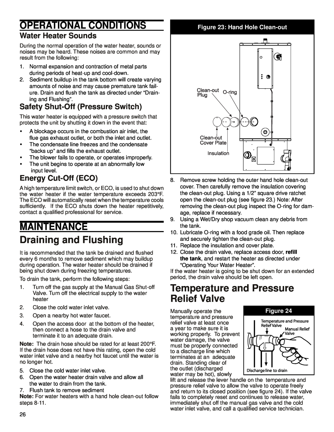
Note: For water heaters with a hand hole
Figure 23: Hand Hole Clean-out
8.Remove screw holding the outer hand hole
9.Using a Wet/Dry shop vacuum clean any debris from the tank.
10.Lubricate
11.Replace the insulation and cover plate.
12.Close the drain valve, replace access door, refill the tank, and restart the heater as directed under
“Operating Your Water Heater”.
If the water heater is going to be shut down for an extended period, the drain valve should be left open.
Temperature and Pressure Relief Valve
Manually operate the temperature and pressure
relief valve at least once a year to make sure it is working properly. To prevent water damage, the valve
must be properly connected to a discharge line which
terminates at an adequate drain. Standing clear of
the outlet (discharged water may be hot), slowly
lift and release the lever handle on the temperature and pressure relief valve to allow the valve to operate freely and return to its closed position (see figure 24). If the valve fails to completely reset and continues to release water, immediately shut off the manual gas valve and the cold water inlet valve, and call a qualified service technician.
26