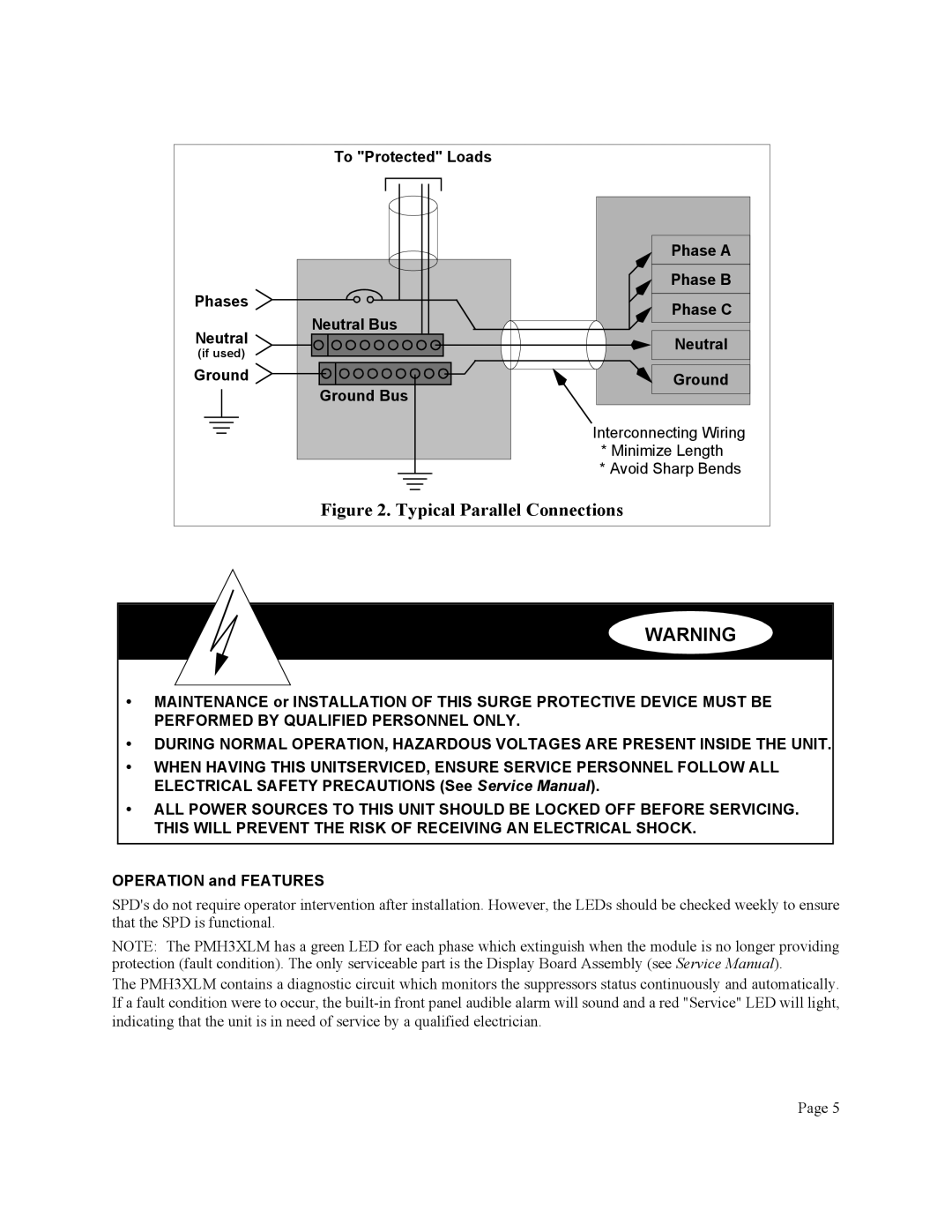
Phases
Neutral
(if used)
Ground ![]()
To "Protected" Loads
Neutral Bus |
Ground Bus |
Phase A |
Phase B |
Phase C |
Neutral |
Ground |
Interconnecting Wiring
*Minimize Length
*Avoid Sharp Bends
Figure 2. Typical Parallel Connections
WARNING
•MAINTENANCE or INSTALLATION OF THIS SURGE PROTECTIVE DEVICE MUST BE PERFORMED BY QUALIFIED PERSONNEL ONLY.
•DURING NORMAL OPERATION, HAZARDOUS VOLTAGES ARE PRESENT INSIDE THE UNIT.
•WHEN HAVING THIS UNITSERVICED, ENSURE SERVICE PERSONNEL FOLLOW ALL ELECTRICAL SAFETY PRECAUTIONS (See Service Manual).
•ALL POWER SOURCES TO THIS UNIT SHOULD BE LOCKED OFF BEFORE SERVICING. THIS WILL PREVENT THE RISK OF RECEIVING AN ELECTRICAL SHOCK.
OPERATION and FEATURES
SPD's do not require operator intervention after installation. However, the LEDs should be checked weekly to ensure that the SPD is functional.
NOTE: The PMH3XLM has a green LED for each phase which extinguish when the module is no longer providing protection (fault condition). The only serviceable part is the Display Board Assembly (see Service Manual).
The PMH3XLM contains a diagnostic circuit which monitors the suppressors status continuously and automatically. If a fault condition were to occur, the
Page 5