APC | User’s Manual |
990-2093 Revision 1 12/00
1 |
| 2 | 3 | Connect Equipment to UPS |
|
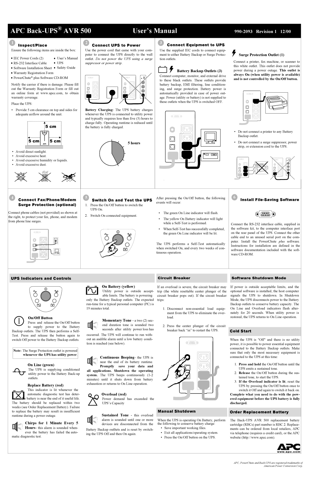
Inspect/Place |
| Connect UPS to Power |
|
| |
Ensure the following items are inside the box: | Use the power cord that came with your com- | Use the supplied IEC cords to connect equip- |
| ||
IEC Power Cords (2) | User’s Manual | puter to connect the UPS directly to the wall | ment to either Battery Backup or Surge Protec- | Surge Protection Outlet (1) | |
outlet. Do not power the UPS using a surge | tion outlets. | Connect a printer, fax machine, or scanner to | |||
UPS | suppressor or power strip. |
|
| ||
|
| this white outlet. This outlet does not provide | |||
Software Installation Sheet | Safety Guide |
|
|
| |
|
| Battery Backup Outlets (3) | power during a power outage. This outlet is | ||
Warranty Registration Form |
|
|
| ||
|
| Connect computer, monitor, and external drive | always On (when utility power is available) | ||
PowerChute® plus Software |
| ||||
| and is not controlled by the On/Off button. | ||||
|
|
| to these black outlets. These outlets provide | ||
Notify the carrier if there is damage. Please fill |
|
| |||
| battery backup, EMI filtering, line condition- |
| |||
out the Warranty Registration Form or fill out |
| ing, and surge protection. Battery power is |
| ||
an online form at www.apcc.com, to obtain |
| automatically provided in case of power out- |
| ||
warranty coverage. |
|
| age. Power (utility or battery) is not supplied to |
| |
Place the UPS: |
|
| these outlets when the UPS is switched OFF. |
| |
|
|
|
|
| |
• Provide 5 cm clearance on top and sides for | Battery Charging: The UPS battery charges |
|
|
| |
adequate airflow around the unit. | whenever the UPS is connected to utility power |
|
|
| |
|
| and typically requires less than five (5) hours to |
|
|
|
|
| charge fully. Operating runtime is reduced until |
|
|
|
|
| the battery is fully charged. |
|
|
|
| • | Do not connect a printer to any Battery |
|
| Backup outlet. |
5 hours | • | Do not connect a surge suppressor, power |
|
| strip, or extension cord to the UPS. |
• Avoid direct sunlight.
• Avoid excessive heat.
• Avoid excessive humidity or liquids.
• Avoid excessive dust.
4 Connect Fax/Phone/Modem | 5 Switch On and Test the UPS | After pressing the On/Off button, the following | 6 |
|
Install | ||||
Surge Protection (optional) | 1. Press the On/Off button to switch the | events will occur: |
|
|
|
|
| ||
Connect phone cables (not provided) as shown at | UPS On. | • The green On Line indicator will flash. |
|
|
2. Switch On connected equipment. |
|
| ||
the right, to protect your fax, phone, and modem | • The yellow On Battery indicator will light |
|
| |
|
|
| ||
from phone line surges. |
|
|
| |
| while a | Connect the | ||
|
| |||
|
| • When | the software kit, to the computer interface port | |
|
| the green On Line indicator will be lit. | on the rear panel of the UPS. Connect the other | |
|
|
| cable end to an unused serial port on the com- | |
|
| The UPS performs a | puter. Install the PowerChute | plus software. |
|
| Instructions for installation are | defined in the | |
|
| when switched On, and every two weeks of con- | ||
|
| software documentation included with the soft- | ||
|
| tinuous operation. | ||
|
| ware |
| |
|
|
|
| |
UPS Indicators and Controls
Circuit Breaker |
| Software Shutdown Mode |
|
|
|
|
|
|
|
|
|
| On Battery (yellow) |
|
| |||||
|
|
|
|
|
|
| Utility power is outside accept- | |||||||
|
|
|
|
|
|
| able limits. The battery is powering | |||||||
|
|
|
|
|
|
| ||||||||
|
|
|
|
|
| only the Battery Backup outlets. The expected | ||||||||
|
|
|
|
|
| |||||||||
|
|
|
|
|
| 19 minutes total. |
|
|
|
|
|
| ||
|
|
| On/Off Button |
| Momentary Tone - a two (2) sec- | |||||||||
|
|
| ||||||||||||
|
|
| Press and | release the On/Off button |
| |||||||||
|
|
|
| ond duration | tone is | sounded | two | |||||||
|
|
| to supply | power to the Battery |
| |||||||||
|
|
|
| seconds | after | utility | power loss has | |||||||
Backup outlets. The UPS then performs a Self- |
| |||||||||||||
occurred. The UPS will continue to run with- | ||||||||||||||
Test. Press and release the button again to | ||||||||||||||
switch Off power to the Battery Backup outlets. | out an audible alarm until a low battery condi- | |||||||||||||
|
|
|
|
|
| tion is reached (see below). |
|
|
|
| ||||
|
|
|
|
|
|
|
|
|
|
|
|
| ||
| Note: The Surge Protection outlet is powered |
|
|
|
|
|
|
|
|
| ||||
|
| whenever the UPS has utility power. |
|
| Continuous Beeping- the UPS is | |||||||||
|
|
|
|
|
|
| ||||||||
|
|
| On Line (green) |
| near the end of its battery runtime. | |||||||||
|
|
|
| Promptly | save | your | data | and | ||||||
|
|
| The UPS is supplying conditioned |
| ||||||||||
|
|
| all applications. Shutdown the | operating | ||||||||||
|
|
| utility power to the Battery | |||||||||||
|
|
| system. The UPS | beeps | continuously | |||||||||
|
|
| outlets. |
|
| |||||||||
|
|
|
|
| minutes) until it shuts down from battery | |||||||||
|
|
|
|
|
| |||||||||
|
|
| Replace Battery (red) | exhaustion or returns to On Line operation. | ||||||||||
|
|
|
|
|
|
|
|
|
|
| ||||
|
|
| This indicator is lit whenever the |
| Overload (red) |
|
|
|
| |||||
|
|
| automatic diagnostic test has deter- |
|
|
|
|
| ||||||
mined th | e battery is near the end of it useful life. |
| Power demand has exceeded the | |||||||||||
The battery should be replaced within two |
| |||||||||||||
| UPS’s Capacity |
|
|
|
| |||||||||
weeks (see Order Replacement Battery). Failure |
|
|
|
|
|
|
|
| ||||||
If an overload is severe, the circuit breaker may trip (the white resettable center plunger of the circuit breaker pops out). If the circuit breaker trips:
1.Disconnect
2.Press the center plunger of the circuit breaker back “in” to restart the UPS.
If power is outside acceptable limits, and the optional software is installed, the host computer signals the UPS to shutdown. In Shutdown Mode, the UPS disconnects power to the Battery Backup outlets to conserve battery capacity. The On Line and Overload indicators flash alter- nately for 20 seconds. When utility power is restored, the UPS returns to On Line operation.
Cold Start
When the UPS is "Off" and there is no utility power, it is possible to power essential equipment connected to the Battery Backup outlets. Make sure that only the most necessary equipment is connected to the UPS at this time:
1.Press and hold the On/Off button until the UPS emits a sustained tone.
2.Release the On/Off button during the sus- tained tone, to start the UPS.
3.If the Overload indicator is lit, reset the
UPS by pressing the On/Off button once to switch it Off and again to switch it back on.
Complete what you need to do with the pow- ered equipment before the UPS battery is fully discharged.
to replace the battery may result in insufficient | Sustained Tone - this overload |
runtime during a power outage. | |
Chirps for 1 Minute Every 5 | alarm is sounded until one or more |
devices are disconnected from the | |
Hours- this alarm is sounded when- | Battery Backup outltets and is reset by switch- |
|
ever the battery has failed the auto- | ing the UPS Off and then On again. | |
matic diagnostic test. | ||
|
Manual Shutdown |
| Order Replacement Battery |
|
|
|
When the UPS is operating On Battery, perform |
| The |
the following to conserve battery charge: |
| cartridge (RBCs) part number is RBC 2. Replace- |
• Save important working files. |
| ments can be ordered from local retailers, APC |
• Exit all applications/operating system. |
| via telephone (requires a credit card), or the APC |
• Press the On/Off button on the UPS. |
| website (http://www.apcc.com). |
APC, PowerChute and