Installation Instructions
3821.631 SERIES
3821.641 SERIES
![]() 3821.634 SERIES SINGLE CONTROL KITCHEN 3821.644 SERIES FAUCET WITH CAST SPOUT
3821.634 SERIES SINGLE CONTROL KITCHEN 3821.644 SERIES FAUCET WITH CAST SPOUT
Thank you for selecting
To ensure that your installation proceeds
Certified to comply with ANSI A112.18.1M
M 9 6 8 1 8 8 E
TOOLS REQUIRED
|
| Phillips Screwdriver |
|
|
|
| Adjustable Wrench | Plumbers' Putty or Caulking |
|
| Channel Locks | Regular Screwdriver | Tubing Cutter | |
|
|
|
| |
1 | INSTALL FAUCET WITH OR WITHOUT DECK ESCUTCHEON |
|
| |
CAUTION Turn off hot and cold water supplies before beginning. |
|
| ||
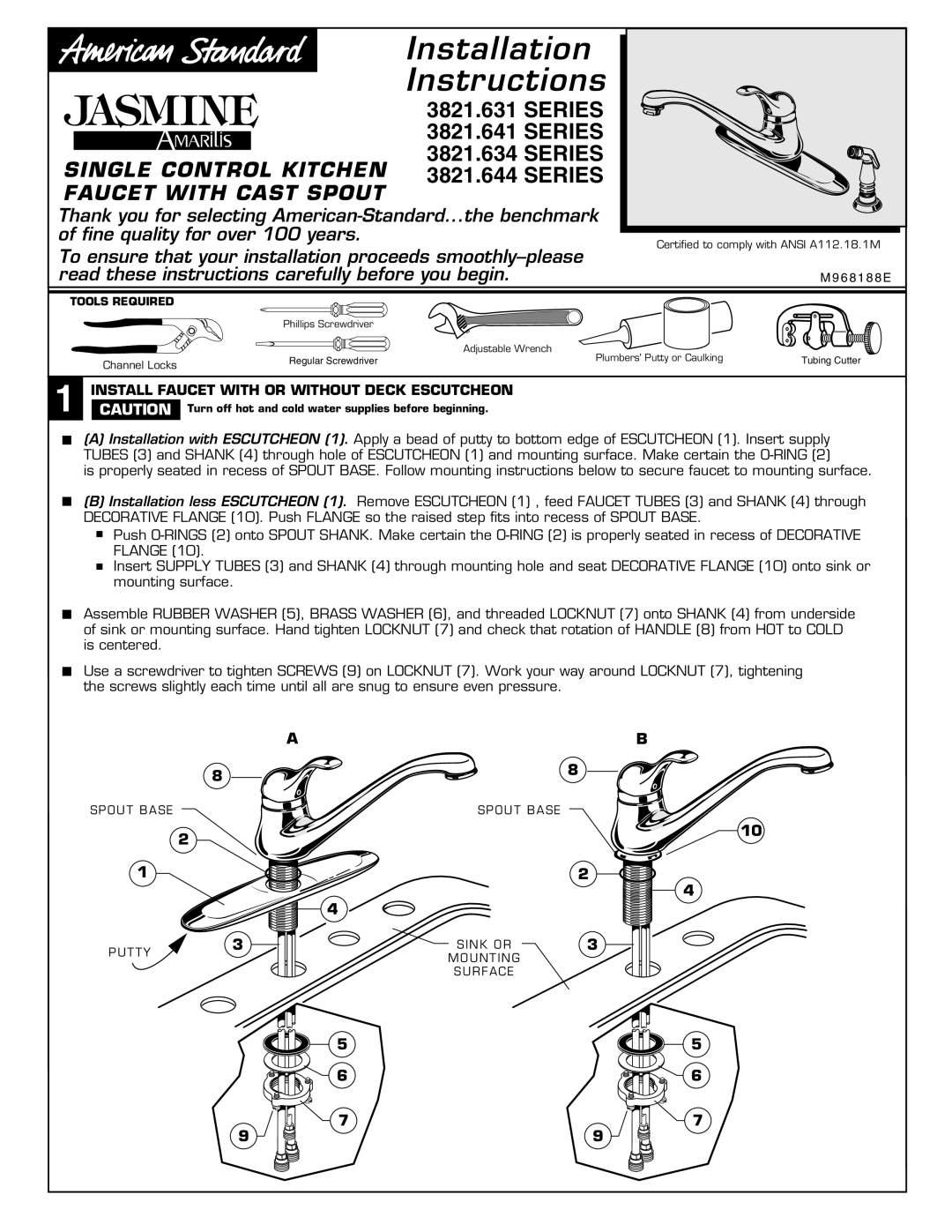
(A) Installation with ESCUTCHEON (1). Apply a bead of putty to bottom edge of ESCUTCHEON (1). Insert supply TUBES (3) and SHANK (4) through hole of ESCUTCHEON (1) and mounting surface. Make certain the
is properly seated in recess of SPOUT BASE. Follow mounting instructions below to secure faucet to mounting surface.
(B) Installation less ESCUTCHEON (1). Remove ESCUTCHEON (1) , feed FAUCET TUBES (3) and SHANK (4) through DECORATIVE FLANGE (10). Push FLANGE so the raised step fits into recess of SPOUT BASE.
Push
Insert SUPPLY TUBES (3) and SHANK (4) through mounting hole and seat DECORATIVE FLANGE (10) onto sink or mounting surface.
Assemble RUBBER WASHER (5), BRASS WASHER (6), and threaded LOCKNUT (7) onto SHANK (4) from underside of sink or mounting surface. Hand tighten LOCKNUT (7) and check that rotation of HANDLE (8) from HOT to COLD is centered.
Use a screwdriver to tighten SCREWS (9) on LOCKNUT (7). Work your way around LOCKNUT (7), tightening the screws slightly each time until all are snug to ensure even pressure.
AB
| 8 |
| 8 |
|
|
| |
SPOUT BASE |
| SPOUT BASE |
|
| 2 |
|
|
1 |
|
| 2 |
|
| 4 |
|
P U T T Y | 3 | SINK OR | 3 |
| MOUNTING |
| |
|
|
|
SURFACE
5
6
| 7 |
9 | 9 |
![]()
![]() 10
10
4
5
6
7