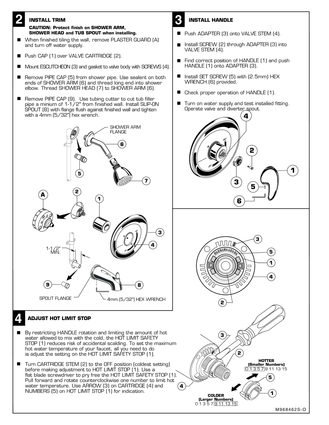
2 INSTALL TRIM
CAUTION: Protect finish on SHOWER ARM,
SHOWER HEAD and TUB SPOUT when installing.
When finished tiling the wall, remove PLASTER GUARD (A) and turn off water supply.
Push CAP (1) over VALVE CARTRIDGE (2).
Mount ESCUTCHEON (3) and gasket to valve body with SCREWS (4).
Remove PIPE CAP (5) from shower pipe. Use sealent on both ends of SHOWER ARM (6) and thread long end into shower elbow. Thread SHOWER HEAD (7) to SHOWER ARM (6).
Remove PIPE CAP (9). Use tubing cutter to cut tub filler pipe a minium of
3 INSTALL HANDLE
Push ADAPTER (3) onto VALVE STEM (4).
Install SCREW (2) through ADAPTER (3) into VALVE STEM (4).
Find correct position of HANDLE (1) and push HANDLE (1) onto ADAPTER (3).
Install SET SCREW (5) with (2.5mm) HEX WRENCH (6) provided.
Check proper operation of HANDLE (1).
Turn on water supply and test installed fitting. Operate valve and diverter spout.
4
SHOWER ARM
FLANGE
6
2
A
5
7
2
3
1
5
1
3
4
6
3 |
9 | 8 |
SPOUT FLANGE | 4mm (5/32") HEX WRENCH |
4 ADJUST HOT LIMIT STOP
|
| 57 | 9 |
|
|
|
|
| 11 | 3 |
| 5 | |
| 3 |
| 1 | |||
1 |
|
|
| |||
0 |
|
|
|
| 51 | |
|
|
|
|
|
| 1 |
|
|
|
|
|
| 4 |
2
By restricting HANDLE rotation and limiting the amount of hot water allowed to mix with the cold, the HOT LIMIT SAFETY STOP (1) reduces risk of accidental scalding. To set the maximum hot water temperature of your faucet, all you need to do
is adjust the setting on the HOT LIMIT SAFETY STOP (1).
Turn CARTRIDGE STEM (2) to the OFF position (coldest setting) before making adjustment to HOT LIMIT STOP (1). Use a
flat blade screwdriver to pry free the HOT LIMIT SAFETY STOP (1). Pull forward and rotate counterclockwise one number to limit hot
water temperature. Use ARROW (3) on CARTRIDGE (4) and 4 NUMBERS (5) on HOT LIMIT STOP (1) for indication.
3
2
|
|
|
|
|
|
| 1 |
|
|
|
|
|
|
| 5 |
|
|
|
|
|
|
| 1 |
|
|
|
|
|
| 1 | 3 |
|
|
|
|
| 1 |
| |
|
|
|
| 9 |
|
| |
|
|
| 7 |
|
|
| |
|
| 5 |
|
|
|
| |
| 3 |
|
|
|
|
| |
1 |
|
|
|
|
|
| |
|
|
|
|
|
|
|
COLDER
(Larger Numbers)
0 1 3 5 7 9 11 13 15
HOTTER
(Smaller Numbers)
0 1 3 5 7 9 11 13 15
5
|
|
|
|
|
| 1 |
|
|
|
|
|
| 5 |
|
|
|
|
|
| 1 |
|
|
|
|
|
| 3 |
|
|
|
|
| 1 | 1 |
|
|
|
| 9 |
| |
|
|
| 7 |
|
| |
|
| 5 |
|
|
| |
| 3 |
|
|
| 1 | |
1 |
|
|
|
| ||
|
|
|
|
| ||
|
|
|
|
|
|
M 9 6 8 4 6 2 S - O