| Installation | |
SWAN | Instructions | |
6011 | ||
IN WALL PRESSURE BALANCING | ||
6012 | ||
BATH AND SHOWER SETS |
Thank you for selecting
To ensure that your installation proceeds
|
|
|
| Certified to comply with ANSI A112.18.1 | ||
|
|
|
|
|
| M 9 6 8 4 6 2 S - O |
| Required Tools |
|
|
| ||
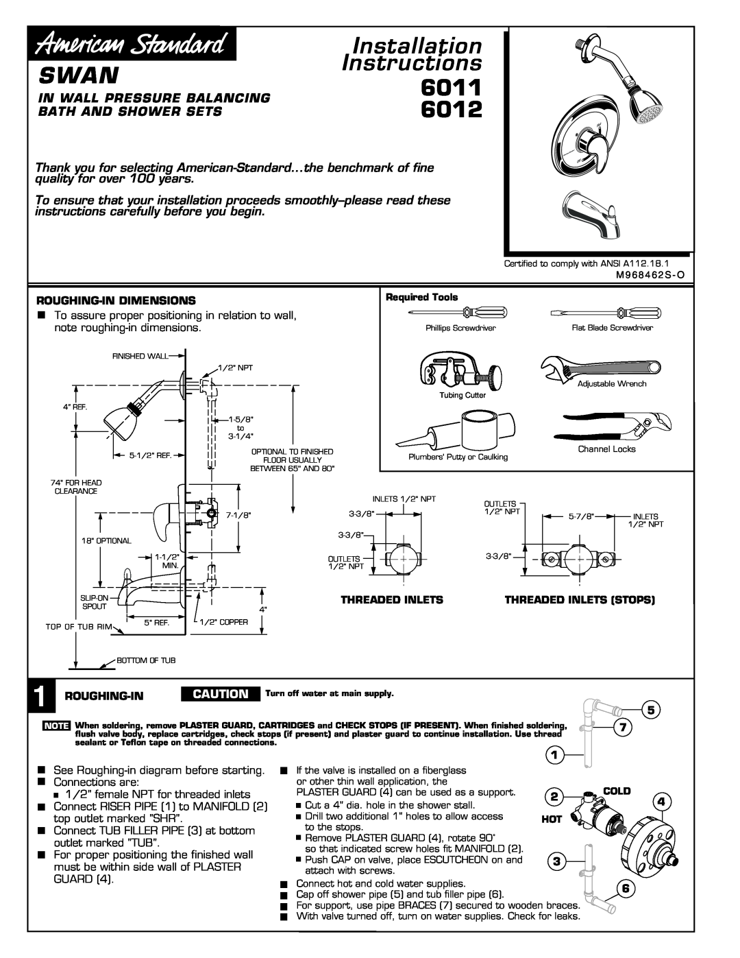
To assure proper positioning in relation to wall, |
|
|
|
| ||
note | Phillips Screwdriver | Flat Blade Screwdriver | ||||
| FINISHED WALL |
|
|
|
|
|
|
| 1/2" NPT |
|
|
|
|
|
|
|
|
| Adjustable Wrench | |
|
|
| Tubing Cutter |
|
| |
4" REF. |
|
|
|
|
|
|
|
|
|
|
|
| |
|
| to |
|
|
|
|
|
|
|
|
|
| |
| OPTIONAL TO FINISHED |
| Channel Locks | |||
| FLOOR USUALLY | Plumbers' Putty or Caulking |
|
| ||
|
|
|
|
|
| |
|
| BETWEEN 65'' AND 80'' |
|
|
| |
74" FOR HEAD |
|
|
|
|
|
|
CLEARANCE |
|
| INLETS 1/2" NPT |
|
|
|
|
|
| OUTLETS |
|
| |
|
|
|
|
|
| |
|
| 1/2" NPT | INLETS | |||
|
|
| ||||
|
|
|
|
|
| 1/2" NPT |
18" OPTIONAL |
|
|
|
| ||
|
|
|
|
| ||
|
| OUTLETS |
|
| ||
| MIN. |
| 1/2" NPT |
|
|
|
|
| THREADED INLETS | THREADED INLETS (STOPS) | |||
SPOUT |
| 4" |
|
|
|
|
|
|
|
|
|
| |
TOP OF TUB RIM | 5" REF. | 1/2" COPPER |
|
|
|
|
|
|
|
|
|
| |
| BOTTOM OF TUB |
|
|
|
|
|
1 |
|
|
|
CAUTION | Turn off water at main supply. | ||
|
|
NOTE When soldering, remove PLASTER GUARD, CARTRIDGES and CHECK STOPS (IF PRESENT). When finished soldering, flush valve body, replace cartridges, check stops (if present) and plaster guard to continue installation. Use thread sealant or Teflon tape on threaded connections.
5
7
See
![]() 1/2" female NPT for threaded inlets Connect RISER PIPE (1) to MANIFOLD (2) top outlet marked "SHR".
1/2" female NPT for threaded inlets Connect RISER PIPE (1) to MANIFOLD (2) top outlet marked "SHR".
Connect TUB FILLER PIPE (3) at bottom outlet marked "TUB".
For proper positioning the finished wall must be within side wall of PLASTER GUARD (4).
1
If the valve is installed on a fiberglass |
| |
or other thin wall application, the |
| |
PLASTER GUARD (4) can be used as a support. | 2 | |
| Cut a 4" dia. hole in the shower stall. | |
|
| |
|
| |
| Drill two additional 1" holes to allow access | HOT |
| ||
| ||
| to the stops. | |
|
| |
| Remove PLASTER GUARD (4), rotate 90˚ |
|
|
| |
|
| |
| so that indicated screw holes fit MANIFOLD (2). |
|
| Push CAP on valve, place ESCUTCHEON on and | 3 |
| ||
| ||
| attach with screws. |
|
Connect hot and cold water supplies.
Cap off shower pipe (5) and tub filler pipe (6).
For support, use pipe BRACES (7) secured to wooden braces. With valve turned off, turn on water supplies. Check for leaks.
COLD
4
6