American Standard 6013 Fig. J, Fig. K, Unlocked Mode, Stopper Installation Procedure, Locked Mode

Models: 6013S 6013

1 7
Download 7 pages 53.03 Kb
Page 6
Image 6
STOPPER INSTALLATION PROCEDURE

STOPPER INSTALLATION PROCEDURE

The Stopper can be installed two ways, “Locked” Mode (Stopper cannot be removed) or “Unlock” Mode (Stopper is removable).
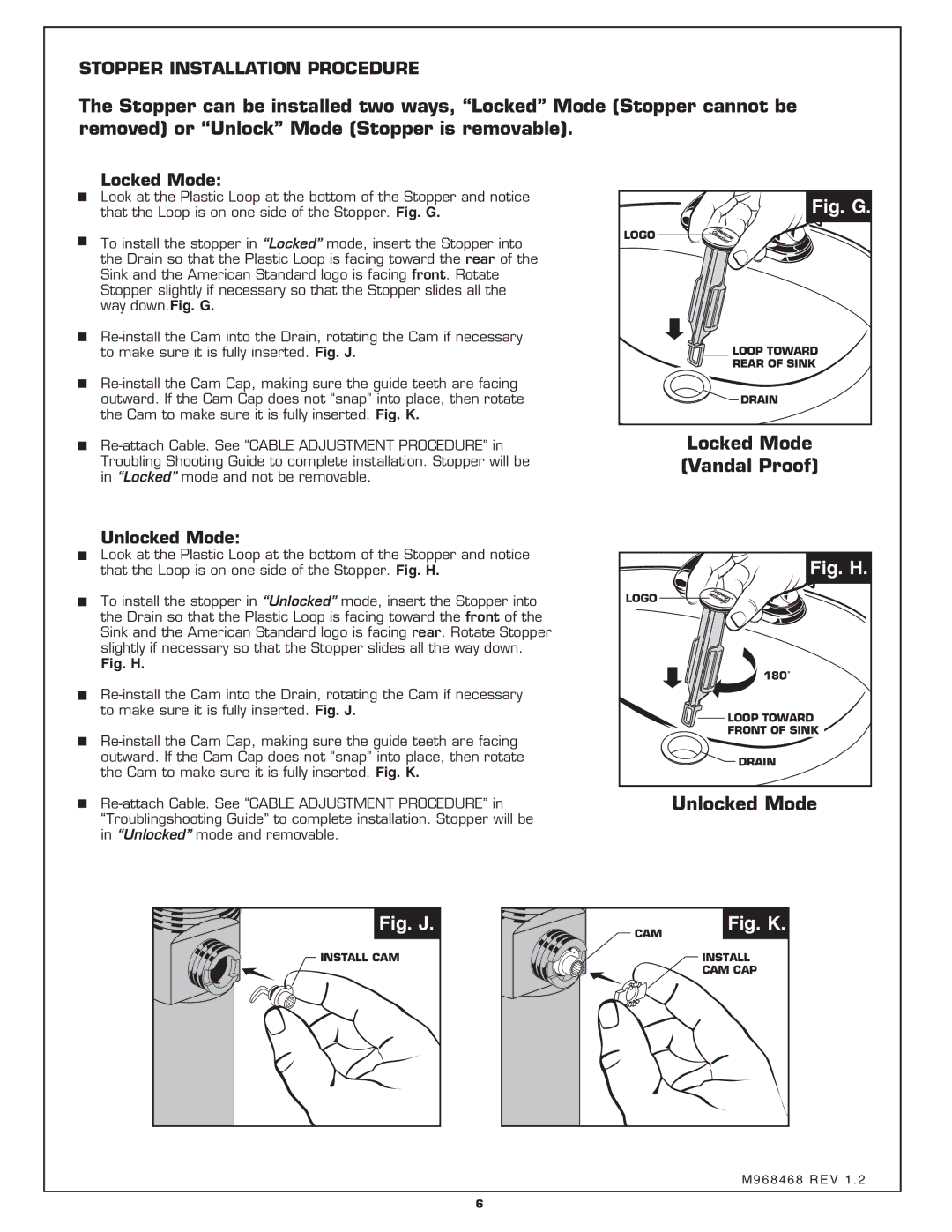
Locked Mode:

Look at the Plastic Loop at the bottom of the Stopper and notice that the Loop is on one side of the Stopper. Fig. G.

To install the stopper in “Locked” mode, insert the Stopper into the Drain so that the Plastic Loop is facing toward the rear of the Sink and the American Standard logo is facing front. Rotate

Stopper slightly if necessary so that the Stopper slides all the way down.Fig. G.

Re-install the Cam into the Drain, rotating the Cam if necessary to make sure it is fully inserted. Fig. J.

Re-install the Cam Cap, making sure the guide teeth are facing outward. If the Cam Cap does not “snap” into place, then rotate the Cam to make sure it is fully inserted. Fig. K.

Fig. G.

LOGO

LOOP TOWARD

REAR OF SINK

DRAIN

Re-attach Cable. See “CABLE ADJUSTMENT PROCEDURE” in Troubling Shooting Guide to complete installation. Stopper will be in “Locked” mode and not be removable.

Unlocked Mode:

Look at the Plastic Loop at the bottom of the Stopper and notice that the Loop is on one side of the Stopper. Fig. H.

To install the stopper in “Unlocked” mode, insert the Stopper into the Drain so that the Plastic Loop is facing toward the front of the

Sink and the American Standard logo is facing rear. Rotate Stopper slightly if necessary so that the Stopper slides all the way down.

Fig. H.

Re-install the Cam into the Drain, rotating the Cam if necessary to make sure it is fully inserted. Fig. J.

Re-install the Cam Cap, making sure the guide teeth are facing outward. If the Cam Cap does not “snap” into place, then rotate the Cam to make sure it is fully inserted. Fig. K.

Re-attach Cable. See “CABLE ADJUSTMENT PROCEDURE” in “Troublingshooting Guide” to complete installation. Stopper will be in “Unlocked” mode and removable.

Locked Mode

(Vandal Proof)

Locked Mode:Fig. H.

LOGO

180˚

Fig. G.Unlocked Mode:Fig. H. LOOP TOWARD

FRONT OF SINK

Fig. J. DRAIN

Unlocked Mode

Fig. J.

CAM

Fig. K.

INSTALL CAM

INSTALL CAM CAP

M968468 REV 1 . 2

6

Page 6
Image 6
American Standard 6013S Fig. J, Fig. K, Unlocked Mode, Stopper Installation Procedure, Locked Mode, Fig. G, Fig. H