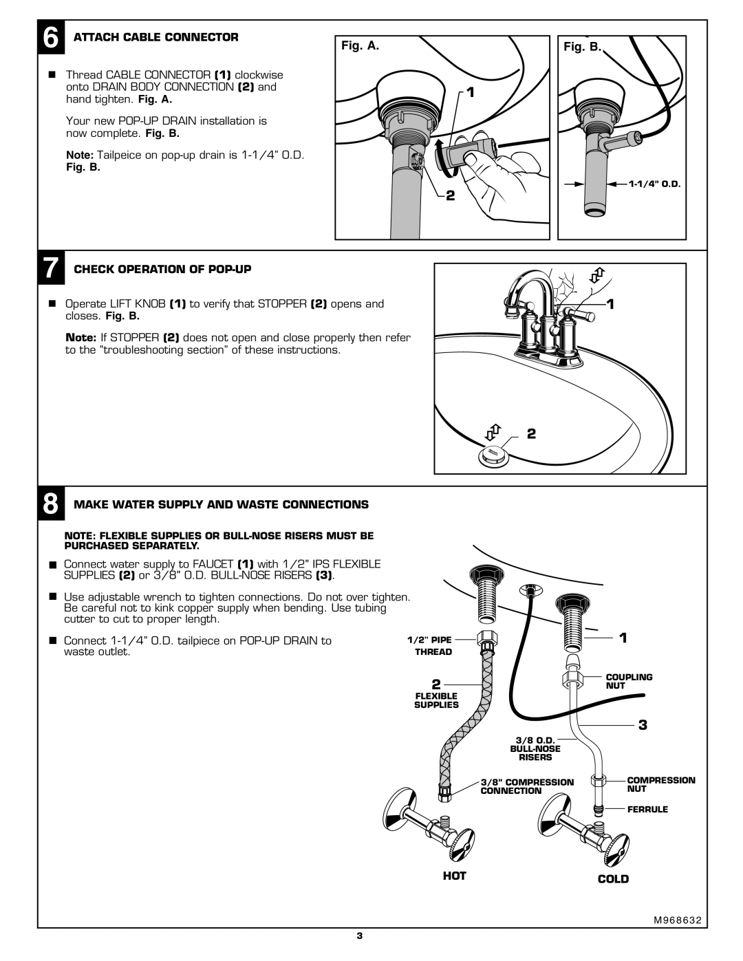
6 ATTACH CABLE CONNECTOR | Fig. A. | Fig. B. |
Thread CABLE CONNECTOR (1) clockwise |
|
|
onto DRAIN BODY CONNECTION (2) and |
| 1 |
hand tighten. Fig. A. |
| |
|
| |
Your new |
|
|
now complete. Fig. B. |
|
|
Note: Tailpeice on |
|
|
Fig. B. |
|
|
|
| |
|
| 2 |
7 CHECK OPERATION OF |
|
Operate LIFT KNOB (1) to verify that STOPPER (2) opens and | 1 |
closes. Fig. B. |
|
Note: If STOPPER (2) does not open and close properly then refer to the “troubleshooting section” of these instructions.
2
8MAKE WATER SUPPLY AND WASTE CONNECTIONS
NOTE: FLEXIBLE SUPPLIES OR
PURCHASED SEPARATELY.
Connect water supply to FAUCET (1) with 1/2" IPS FLEXIBLE
SUPPLIES (2) or 3/8" O.D.
Use adjustable wrench to tighten connections. Do not over tighten. Be careful not to kink copper supply when bending. Use tubing cutter to cut to proper length.
Connect
1/2" PIPE | 1 |
THREAD |
|
2 | COUPLING |
NUT | |
FLEXIBLE |
|
SUPPLIES |
|
| 3 |
3/8 O.D. |
|
| |
RISERS |
|
3/8” COMPRESSION | COMPRESSION |
CONNECTION | NUT |
| FERRULE |
HOTCOLD
M 9 6 8 6 3 2
3