Appendix B – Connector Pinouts
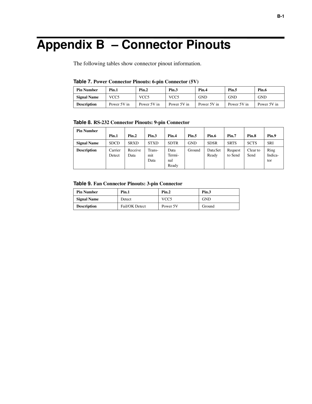
The following tables show connector pinout information.
Table 7. Power Connector Pinouts:
Pin Number | Pin.1 | Pin.2 | Pin.3 | Pin.4 | Pin.5 | Pin.6 |
|
|
|
|
|
|
|
Signal Name | VCC5 | VCC5 | VCC5 | GND | GND | GND |
|
|
|
|
|
|
|
Description | Power 5V in | Power 5V in | Power 5V in | Power 5V in | Power 5V in | Power 5V in |
|
|
|
|
|
|
|
Table 8. RS-232 Connector Pinouts: 9-pin Connector
Pin Number | Pin.1 | Pin.2 | Pin.3 | Pin.4 | Pin.5 | Pin.6 | Pin.7 | Pin.8 | Pin.9 |
| |||||||||
|
|
|
|
|
|
|
|
|
|
Signal Name | SDCD | SRXD | STXD | SDTR | GND | SDSR | SRTS | SCTS | SRI |
|
|
|
|
|
|
|
|
|
|
Description | Carrier | Receive | Trans- | Data | Ground | Data Set | Request | Clear to | Ring |
| Detect | Data | mit | Termi- |
| Ready | to Send | Send | Indica- |
|
|
| Data | nal |
|
|
|
| tor |
|
|
|
| Ready |
|
|
|
|
|
|
|
|
|
|
|
|
|
|
|
Table 9. Fan Connector Pinouts: 3-pin Connector
Pin Number | Pin.1 | Pin.2 | Pin.3 |
|
|
|
|
Signal Name | Detect | VCC5 | GND |
|
|
|
|
Description | Fail/OK Detect | Power 5V | Ground |
|
|
|
|