68 Web User Guide
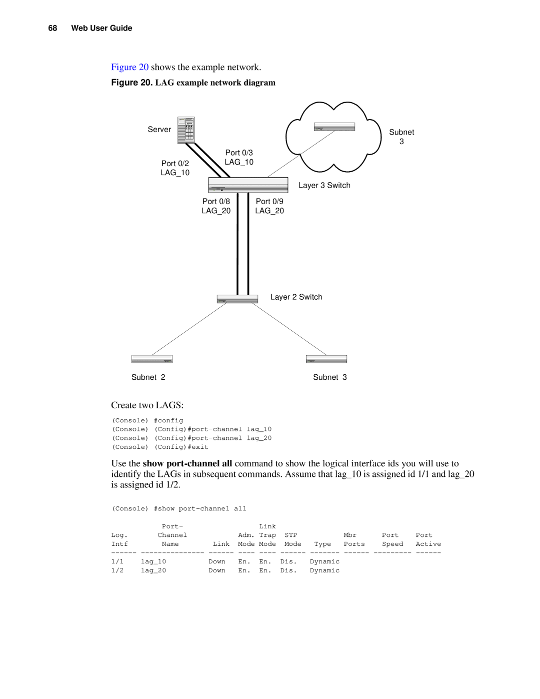
Figure 20 shows the example network.
Figure 20. LAG example network diagram
Server
Port 0/3
Port 0/2 LAG_10
LAG_10
Layer 3 Switch
Port 0/8 | Port 0/9 |
LAG_20 | LAG_20 |
Layer 2 Switch
Subnet 2 | Subnet 3 |
Subnet
3
Create two LAGS:
(Console) #config
(Console)
(Console)
(Console) (Config)#exit
Use the show
(Console) #show |
|
|
|
|
|
| |||
Log. | Port- |
| Adm. | Link | STP |
| Mbr | Port | Port |
Channel | Link | Trap | Type | ||||||
Intf | Name | Mode | Mode | Mode | Ports | Speed | Active | ||
1/1 | lag_10 | Down | En. | En. | Dis. | Dynamic |
|
|
|
1/2 | lag_20 | Down | En. | En. | Dis. | Dynamic |
|
|
|
