13 CHECK ALL ELECTRICAL AND PLUMBING CONNECTIONS
1.Turn on water supplies and check for leaks. Tighten any connections if necessary.
2.Check FAUCET operation, if adjustment is required refer to the installation instructions shown at right supplied with the ICU FAUCET. No.
M965119.
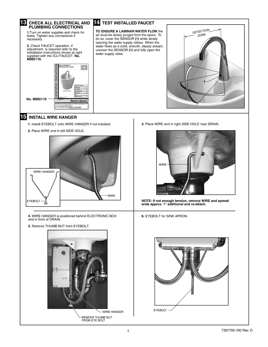
14 TEST INSTALLED FAUCET
TO ENSURE A LAMINAR WATER FLOW the air must be slowly purged from the spout. To do so, cover the SENSOR (1) while slowly opening the water supply valves. When the water flows as a solid, smooth, steady stream, uncover the SENSOR (1) and fully open the water supply valve.
DETECTION  ZONE
ZONE
| Instructions | SELECTRONIC™ | MODEL NUMBERS | |
|
| Proximity ICU Faucet | 6055.193 | |
|
|
| 6056.193 | |
| Installation |
|
| 1 |
| M 9 6 5 119 | Product No.'s & Options | 1 | |
|
|
| Specifications | 2 |
|
|
| How to Install | |
|
| 6055 / 6056 ICU Faucet shown Installed on | Electrical | |
|
| American Standard 9118.111 ICU Sink | ||
|
|
| Maintenance | |
|
|
| FAQ,s | 9 |
No. M965119 |
|
| Replacement Parts | 10 |
| © 2011 American Standard |
|
| |
NOTE TO INSTALLER: Please give this manual to the customer after installation.
To learn more about American Standard Faucets visit our website at: www.us.amstd.com or U.S.
customer's
For Parts, Service, Warranty or other Assistance,
please call
15 INSTALL WIRE HANGER |
|
1. Install EYEBOLT onto WIRE HANGER if not installed. | 3. Place WIRE end in right SIDE HOLE near DRAIN. |
2.Place WIRE end in left SIDE HOLE.
| WIRE |
WIRE HANGER |
|
| WIRE |
EYEBOLT | NOTE: If not enough tension, remove WIRE and spread |
| ends approx. 1" additional and |
4. WIRE HANGER is positioned behind ELECTRONIC BOX | 6. EYEBOLT for SINK APRON. |
and in front of DRAIN. |
|
5.Remove THUMB NUT from EYEBOLT.
WIRE HANGER
REMOVE THUMB NUT
FROM EYE BOLT
EYEBOLT
5 |