Manuals
/
American Water Heater
/
Household Appliance
/
Water Heater
American Water Heater
VG6250T76NV Series 100, American Water Heaters Residential Gas Water Heater
Models:
American Water Heaters Residential Gas Water Heater
VG6250T76NV Series 100
1
28
40
40
Download
40 pages
53.76 Kb
25
26
27
28
29
30
31
32
<
>
Troubleshooting
Install
Repair Parts List
Parts list
Power Vent Wiring Schematic - Figure
Replacement Parts And Deliming Products
Warranty
Maintenance
Problem
Vent Pipe Assembly
Page 28
Image 28
28
Page 27
Page 29
Page 28
Image 28
Page 27
Page 29
Contents
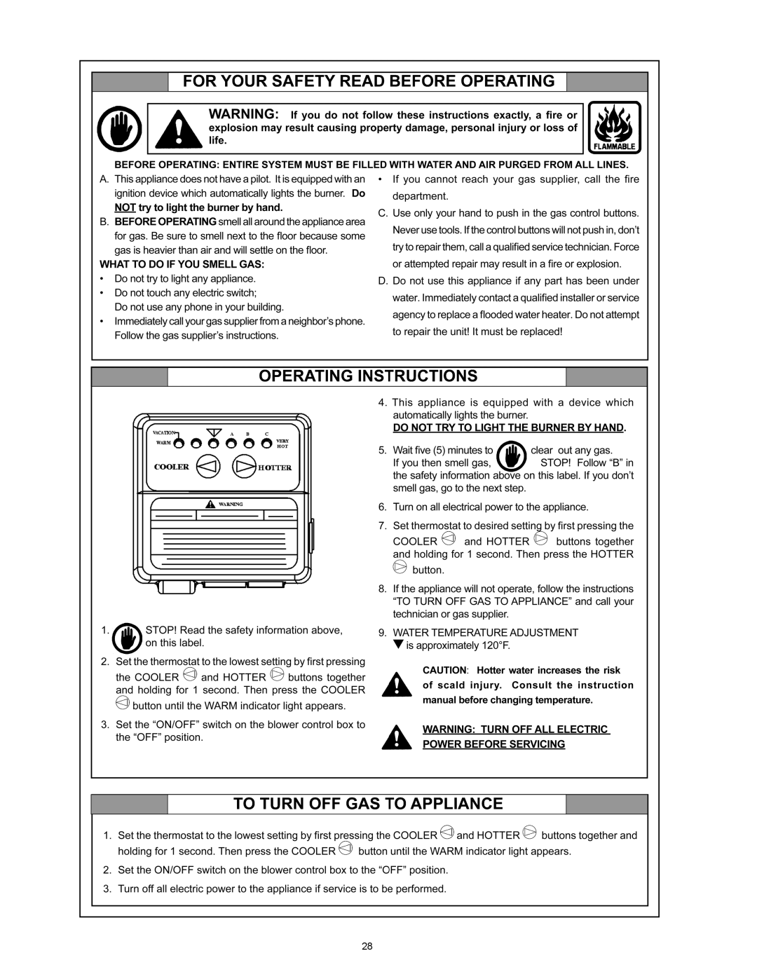
For Your Safety
whenever maintenance adjustment or service is required
RESIDENTIAL GAS WATER HEATERS
Instruction Manual
SAFE INSTALLATION, USE AND SERVICE
APPROVALS
IMPORTANT DEFINITIONS
DANGER
GENERAL SAFETY INFORMATION
GENERAL SAFETY INFORMATION
TABLE OF CONTENTS
Qualified Installer or Service Agency
Preparing for the Installation
INTRODUCTION
INSTALLATION OF CARBON MONOXIDE DETECTORS
Commonwealth of Massachusetts
APPROVED CARBON MONOXIDE DETECTORS
SIGNAGE
TYPICAL INSTALLATION
REPLACEMENT PARTS AND DELIMING PRODUCTS
GET TO KNOW YOUR WATER HEATER - GAS MODELS
O Inlet Dip Tube P Temperature & Pressure Relief Valve
TYPICAL INSTALLATION
CONDENSATE HOSE AND DRAIN PAN
FIGURE 1A
DANGER
MIXING VALVE / THERMAL EXPANSION TANK USAGE AND SPACE HEATING
Mixing Valves
TYPICAL INSTALLATION
LOCATING THE NEW WATER HEATER
Facts to Consider About the Location
INSULATION BLANKETS
Air REQUIREMENTs
Unconfined Space
CONFINED SPACE
Fresh Air Openings For Confined Spaces
Outdoor Air Through Two Openings
OUTDOOR AIR THROUGH TWO HORIZONTAL DUCTS
OUTDOOR AIR THROUGH TWO VERTICAL DUCTS
AIR FROM OTHER INDOOR SPACES
FIGURE 9A
INSTALLING THE NEW WATER HEATER
CHEMICAL VAPOR CORROSION
Water Piping
SPACE HEATING AND POTABLE WATER SYSTEM
Temperature-Pressure Relief Valve
Explosion Hazard
Thermal Expansion
T & P Valve and Pipe Insulation
HIGH ALTITUDE INSTALLATION
Water Damage Hazard
Fire and Explosion Hazard
Gas Piping
SEDIMENT TRAPS
Filling the Water Heater
FLEXIBLE CONNECTOR
FIGURE 12. GAS PIPING WITH
VENT PIPE ASSEMBLY
VENTING
Termination Clearances Sidewall Power Vent
VENT PIPE TERMINATION
PLANNING THE VENT SYSTEM
CONDENSATE
Breathing Hazard - Carbon Monoxide Gas
If using 2” inch vent pipe
INSTALLATION OF VENT SYSTEM
BLOWER ASSEMBLY INSTALLATION
VENT TERMINAL INSTALLATION, SIDEWALL
POWER VENT WIRING SCHEMATIC - FIGURE
SEQUENCE OF INSTALLATIONS, FIGURE
VENT TERMINATION - FIGURE
INSTALLATION OF VENT SYSTEM, SIDEWALL
INSTALLATION OF VERTICAL VENT SYSTEM
VENT ATTENUATION ASSEMBLY INSTALLATION INSTRUCTIONS
VENT ATTENUATION ASSEMBLY KIT PARTS LIST
VENT ATTENUATION ASSEMBLY INSTALLATION
Breathing Hazard - Carbon Monoxide Gas
FIGURE 23 Typical Horizontal Installation
Installation for VAA with 3 & 4 inch Pipe for Vertical Vent
3 inch vent Vertical VAA Installations
4 inch vent Vertical VAA Installations
VENT PIPE PREPARATION
RECOMMENDED BRUSH* SIZE FOR PRIMER AND CEMENT APPLICATIONS
1. INITIAL PREPARATION
2. SELECTION OF MATERIALS
D. Inspection, cleaning, priming
STEP E F. Joint assembly
STEP F G. Cleanup and joint movement
B. Deburring
Page
TEMPERATURE REGULATION
GAS CONTROL VALVE - FRONT VIEW
Water Temperature
Time to Produce
PERIODIC MAINTENANCE
FOR YOUR INFORMATION
START UP CONDITIONS
OPERATIONAL CONDITIONS
Burner Cleaning
Burner OPERATION AND Inspection
Housekeeping
ANODE ROD INSPECTION
Temperature-Pressure Relief Valve Test
DRAINING AND FLUSHING
Burn hazard
Hot water discharge
Service
LEAKAGE CHECKPOINTS
REPAIR PARTS LIST
Control Valve Assembly
Blower Assembly
Switch and Harness Assembly
TROUBLESHOOTING GUIDELINES
PROBLEM
SOLUTION
LED STATUS
SOLUTION
PROBLEM
LED STATUS
TROUBLESHOOTING GUIDELINES
These guidelines should be utilized by a qualified service agent
Page
Limited Warranty
FILL IN WARRANTY AND KEEP FOR FUTURE REFERENCE
PO Box 1597, 500 Princeton Road Johnson City, TN Phone
American Water Heater Product Service and Support
Copyright 2013 American Water Heater Company. All rights reserved