Never use this water heater unless it is completely full of water. To prevent damage to the tank, the tank must be filled with water. Water must flow from the hot water faucet before turning “ON” gas to the water heater.
To fill the water heater with water:
1.Close the water heater drain valve by turning handle to the right
(clockwise). The drain valve is on the lower front of water heater.
2.Open the cold water supply valve to the water heater.
NOTE: The cold water supply valve must be left open when the water heater is in use.
3.To insure complete filling of the tank, allow air to exit by opening nearest hot water faucet. Allow water to run until a constant flow is obtained.
This will let air out of the water heater and the piping.
4.Check all water piping and connections for leaks. Repair as needed.
VENT PIPE ASSEMBLY
There are three parts of the vent pipe assembly that connect the water heater exhaust (located on lower back side of water heater) to inlet of the blower assembly (mounted on top of water heater) as shown in Figure
1.These parts will need to be assembled according to the instructions in the VENT PIPE PREPARATION section of this manual. These PVC parts should be assembled with ASTM
Assemble Vent Pipe Assemblies #1, #2 and #3 (See Figure 1) prior to cementing. The preferred orientation of Vent Pipe Assembly #1 (Condensate
see Figure 16. Disassemble the parts and cement back together using the alignment marks. After the cement dries, attach the assembly to the blower and the water heater exhaust using the supplied rubber boots and hose clamps.
Acondensate trap is incorporated in the bottom of this vent pipe assembly. See the CONDENSATE section of this manual for further details.
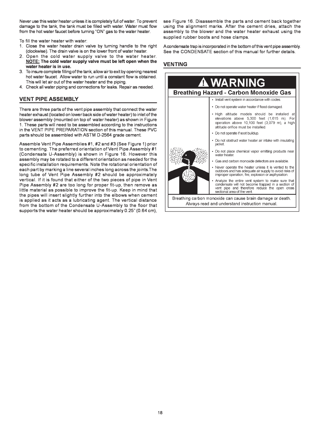
VENTING
18