TROUBLESHOOTING GUIDELINES
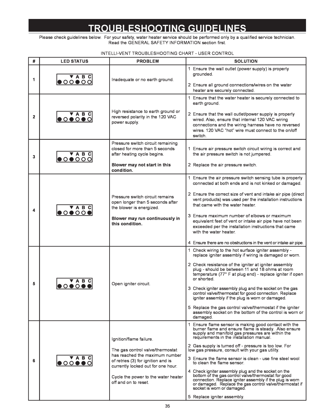
Please check guidelines below. For your safety, water heater service should be performed only by a qualified service technician.
Read the GENERAL SAFETY INFORMATION section first.
#
1
2
3
4
5
6
LED STATUS | PROBLEM |
| SOLUTION | |
|
|
| 1 | Ensure the wall outlet (power supply) is properly |
|
| Inadequate or no earth ground. |
| grounded. |
|
|
| ||
|
| 2 | Ensure all ground connections/wires on the water | |
|
|
| ||
|
|
| ||
|
|
|
| heater are securely connected. |
|
|
| 1 | Ensure that the water heater is securely connected to |
|
|
|
| earth ground. |
|
| High resistance to earth ground or | 2 | Ensure that the wall outlet/power supply is properly |
|
| |||
|
| reversed polarity in the 120 VAC | ||
|
|
| wired. Also, ensure that internal 120 VAC wiring | |
|
| power supply. |
| |
|
|
| connections and the wiring harness have no reversed | |
|
|
|
| |
|
|
|
| wires. 120 VAC “hot” wire must connect to the on/off |
|
|
|
| switch. |
|
| Pressure switch circuit remaining |
|
|
|
| closed for more than 5 seconds | 1 | Ensure air pressure switch circuit wiring is correct and |
|
| after heating cycle begins. |
| the air pressure switch is not jumpered. |
|
| Blower may not start in this | 2 | Replace the air pressure switch. |
|
| |||
|
| condition. |
|
|
|
|
| 1 | Ensure the air pressure switch sensing tube is properly |
|
|
|
| connected at both ends and is not kinked or damaged. |
|
| Pressure switch circuit remains | 2 | Ensure the correct size of vent and intake air pipe (direct |
|
|
| vent products) was used per the installation instructions | |
|
| open longer than 5 seconds after |
| |
|
|
| that came with the water heater. | |
|
| the blower is energized. |
| |
|
|
|
| |
|
| Blower may run continuously in | 3 | Ensure maximum number of elbows or maximum |
|
| |||
|
|
| equivalent feet of vent or intake air pipe have not been | |
|
| this condition. |
| |
|
|
| exceeded per the installation instructions that came | |
|
|
|
| |
|
|
|
| with the water heater. |
|
|
| 4 | Ensure there are no obstructions in the vent or intake air pipe. |
|
|
| 1 | Check wiring to the hot surface igniter assembly - |
|
|
|
| replace igniter assembly if wiring is damaged or worn. |
|
|
| 2 | Check resistance of the igniter at igniter assembly |
|
|
|
| plug - should be between 11 and 18 ohms at room |
|
|
|
| temperature (77° F at plug end) - replace igniter if open |
|
| Open igniter circuit. |
| or shorted. |
|
|
| ||
|
| 3 | Check igniter assembly plug and the socket on the gas | |
|
|
| ||
|
|
| ||
|
|
|
| control valve/thermostat for good connection. Replace |
|
|
|
| igniter assembly if the plug is worn or damaged. |
|
|
| 5 | Replace the gas control valve/thermostat if the igniter |
|
|
|
| assembly socket on the bottom of the control is worn or |
|
|
|
| damaged. |
|
|
| 1 | Ensure flame sensor is making good contact with the |
|
|
|
| burner flame and ensure flame is steady. Also ensure |
|
|
|
| supply and manifold gas pressures are within the |
|
| Ignition/flame failure. |
| requirements in the installation manual. |
|
|
|
| |
|
| The gas control valve/thermostat | 2 | Gas supply is turned off - pressure is too low. For |
|
| low gas pressure, consult with your gas utility. | ||
|
| has reached the maximum number | 3 | Ensure the flame sensor is clean - use fine steel wool |
|
| |||
|
| of retries (3) for ignition and is | ||
|
|
| to clean the flame sensor. | |
|
| currently locked out for one hour. |
| |
|
| 4 | Check igniter assembly plug and the socket on the | |
|
|
| ||
|
| Cycle the power to the water heater |
| bottom of the gas control valve/thermostat for good |
|
| off and on to reset. |
| connection. Replace igniter assembly if the plug is worn |
|
|
| or damaged. Replace the gas control valve/thermostat if | |
|
|
|
| socket is worn or damaged. |
|
|
| 5 | Replace igniter assembly. |
|
|
|
|
|
35