27
INSTALLATION OF HORIZONTAL THROUGH THE WALL VENT SYSTEMIf you are in stal lin g your syste m so tha t it ven ts th roug h roo f, ple ase
refe r to sec tio n tit led VE RTIC AL VE NT TER MIN AL IN STAL LATI ON.
VENT TERMINAL INSTALLATION, SIDEWALL
1. I nsta ll the vent t ermi nal by usin g the co ver pl ate as a temp late to
mark the hole for the vent pipe to pass through the wall. BEWARE
OF CONCEALED WIRING A ND PIPING INSIDE THE WALL.
2. If the Vent Terminal is being installed on the outside of a nished
wall, it may be easier to mark both the inside and outside wall.
Align the holes by drillin g a hole throug h the center of the
template from the inside through to the outside. Th e template
can now be positioned on the outside wall using the drilled hole
as a centering point for the template.
3. A) MASONRY SIDE WALLS
C hisel an opening app roximately one half inc h (1.3 cm) larger
than the marked circle.
B) WOO DEN SIDE WALLS
D ril l a pilo t hol e appr oxim ate ly one quar ter in ch (0. 64 cm) outsi de
of the marked circl e. This pilot hole is used as a starting point
for a saws-all or sabre saw blade. Cut around the marked circle
staying approximately one quarter inch (0.64 cm) outside of the
line. (This will allow the vent to easily slide through the opening.
The resulting gap will be covered up by the Vent Terminal cover
plate.) Repeat this step on inside wall if necessar y.
Cut a length of pipe about 3.5 inches (8.9 cm) longer than the wall
thi ckne ss at th e open ing . Glue the ven t term inal to this sect ion of pipe.
Slide the wall plate over the pipe to stop aga inst the vent ter minal.
Place a bead of caulking (not supplied) around the gap between the
pipe and cover plate. Appl y enough to ll some of the gap between
the pipe and wall. Place some of the caulking on the back of the plate
to hold it against the wall after installation. If the vent pipe is installed
up to the wall, with a coupling on the end against the wall o pening,
the pipe with the vent terminal can b e prepared for gluing before
inserting through the wall. Sli de the pipe through the wall and insert
into the coupling on the other side of the wall, making sure that t he
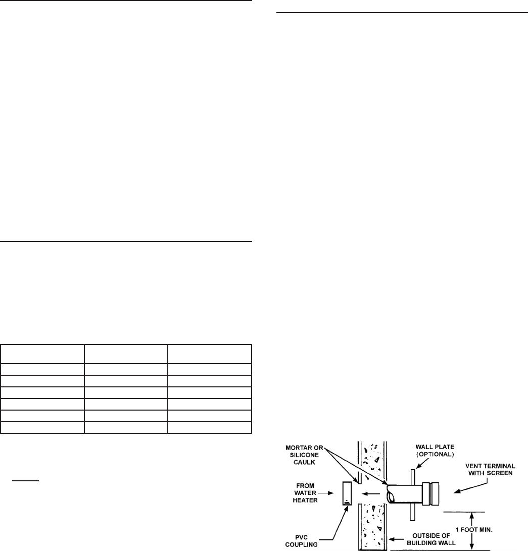
vent terminal ends up pointed in the correct position, see Figu re 12.
Figure 12: VENT TERMINATION
VENT PIPE TERMINATIONThe rst step is to determine where the vent pipe will terminate. See
Figures 12, “Figure: 13A”, and “Figure: 14”. The vent may terminate
thr ough a sidew all as show n in Fig ure 12 an d “Fig ure: 14” or thr oug h
the roof as shown in “Figure: 15” and “Figure: 16”.
The vent system must terminate so that proper clearances are
maintained as cited in local codes or the current e dition of the
National Fuel Gas C ode, (ANSI Z223.1, 12.9.1 through 12.9.4) or
the N atur al Gas and Pr opan e Inst all atio n Cod e (CAN /CS A-B 149.1).
See “Figure: 15” and “Figure: 16”.
Instructions on proper installat ion through a sidewall are provided
in Figures 12, “Figure: 13A”, and “Figure: 14”.
Plan the vent system layout so that proper clea rances are
maintained from plumbing and wir ing.
Vent pipes ser ving power vented water heaters are classied by
building codes as vent connectors. Required clear ances from
combustible mate rials must be provided in acc ordance with
information in this manual under FACTS TO CONSIDER ABOUT
LOCATION and INSTALLING THE WATER HEATER, and with the
National Fuel Gas Code and local co des.
PLANNING THE VENT SYSTEMPlan the ro ute of the vent system from the exhaust elbow to the
planned location of the vent terminal.
1. Layout total vent system to use a minimum of vent pipe and
elbows.
2. This water heater is capable of venting ue gases in equivalent
feet of pipe as listed in Table 7.
Table 7
Number of
90° Elbows
2” Maximum
Pipe - ft. (m)
3” Maximum
Pipe - ft. (m)
140 (12.19) 120 (36.57)
235 (10.66) 115 (35.05)
330 (9.14) 110 (33.52)
425 (7.62) 105 (32)
5 20 (6.09) 100 (30.48)
615 (4.57) 95 (28.95)
The minimum vent length for each of the pipe size is one 90° elbow
plus 2’ and 7’ (0.61 m and 2.1 m) of straight pipe for air intake and
exhaust vent respectively and the appropr iate termination.
NOTE: The eq uiva len t feet (m) of pip e list ed ab ove ar e excl usiv e
of the termination. That is, the termination, with an installed
screen, is as sumed to be i n the system a nd the remainder of
the system must not exce ed the lengths and numb er of elbows
shown in Table 7.
If using 2 ” inch vent pipe: A 2” diameter vent pipe must be
inserted and glued to the exhaust elbow a ssembly.
If using 3” inch vent pipe: Two inches (5.1cm) of 2” diameter pipe
must be inserted and glued to the exhaust elbow assembly before
adding a 2’ x 3” reducer to acquire the desired pipe diameter. A
3” coupling (supplied locally-a schedule 40 DWV) vent terminal
must be obtained. A 3” diameter scr een is supplied in the vent
kit.