SVT-CL 

The Rear Panel Controls and Their Use
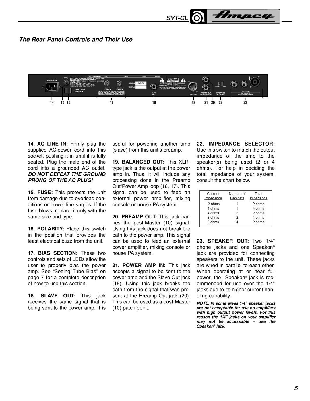
14 | 15 | 16 | 17 | 18 | 19 | 21 | 20 | 22 | 23 |
14.AC LINE IN: Firmly plug the supplied AC power cord into this socket, pushing it in until it is fully seated. Plug the male end of the cord into a grounded AC outlet.
DO NOT DEFEAT THE GROUND PRONG OF THE AC PLUG!
15.FUSE: This protects the unit from damage due to overload con- ditions or power line surges. If the fuse blows, replace it only with the same size and type.
16.POLARITY: Place this switch in the position that provides the least electrical buzz from the unit.
17.BIAS SECTION: These two controls and sets of LEDs allow the user to properly bias the power amp. See “Setting Tube Bias” on page 7 for a complete description of how to use this section.
18.SLAVE OUT: This jack receives the same signal that is being sent to the power amp. It is
useful for powering another amp (slave) from this unit’s preamp.
19.BALANCED OUT: This XLR- type jack is the output at the power amp in. Thus, it will include any processing done in the Preamp Out/Power Amp loop (16, 17). This signal can be used to feed an external power amplifier, mixing console or house PA system.
20.PREAMP OUT: This jack car- ries the
21.POWER AMP IN: This jack accepts a signal to be sent to the power amp and the Slave Out jack (18). Using this jack breaks the path from the signal that was pre- sent at the Preamp Out jack (20). This can be used as a
22.IMPEDANCE SELECTOR: Use this switch to match the output impedance of the amp to the speaker(s) being used (2 or 4 ohms). For help in deciding the total impedance of your system, consult the chart below.
Cabinet | Number of | Total |
Impedance | Cabinets | Impedance |
2 ohms | 1 | 2 ohms |
4 ohms | 1 | 4 ohms |
4 ohms | 2 | 2 ohms |
8 ohms | 2 | 4 ohms |
8 ohms | 4 | 2 ohms |
|
|
|
23.SPEAKER OUT: Two 1/4” phone jacks and one Speakon® jack are provided for connecting speakers to the unit. These jacks are wired in parallel to each other. When operating at or near full power, the Speakon® jack is rec- ommended for use over the 1/4” jacks due to its higher current han- dling capability.
NOTE: In some areas 1/4” speaker jacks are not acceptable for use on amplifiers with high output power levels. For this reason the 1/4” jacks on your amplifier may not be accessable – use the Speakon® jack.
5
