ATM 300 Series | Switches and Indicators |
|
|
1.6Switches and Indicators
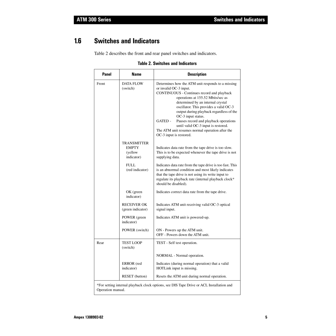
Table 2 describes the front and rear panel switches and indicators.
Table 2. Switches and Indicators
Panel | Name | Description |
|
|
|
Front | DATA FLOW | Determines how the ATM unit responds to a missing |
| (switch) | or invalid |
|
| CONTINUOUS - Continues record and playback |
|
| operations at 155.52 Mbits/sec as |
|
| determined by an internal crystal |
|
| oscillator. This provides a valid |
|
| output during playback regardless of the |
|
| |
|
| GATED - Pauses record and playback operations |
|
| until valid |
|
| The ATM unit resumes normal operation after the |
|
| |
| TRANSMITTER |
|
| EMPTY | Indicates data rate from the tape drive is too slow. |
| (yellow | This is to be expected whenever the tape drive is not |
| indicator) | supplying data. |
| FULL | Indicates data rate from the tape drive is too fast. This |
| (red indicator) | is an abnormal condition and most likely indicates |
|
| that the tape drive is not using its write input to |
|
| regulate its playback rate (internal playback clock* |
|
| should be disabled). |
| OK (green | Indicates correct data rate from the tape drive. |
| indicator) |
|
| RECEIVER OK | Indicates ATM unit receiving valid |
| (green indicator) | signal input. |
| POWER (green | Indicates ATM unit is |
| indicator) |
|
| POWER (switch) | ON - Powers up the ATM unit. |
|
| OFF - Powers down the ATM unit. |
|
|
|
Rear | TEST LOOP | TEST - Self test operation. |
| (switch) |
|
|
| NORMAL - Normal operation. |
| ERROR (red | Indicates (during normal operation) that a valid |
| indicator) | HOTLink input is missing. |
| RESET (button) | Resets the ATM unit during normal operation. |
|
|
|
*For setting internal playback clock options, see DIS Tape Drive or ACL Installation and Operation manual.
Ampex | 5 |