Chapter 2 | Product Overview |
Jumper Definitions
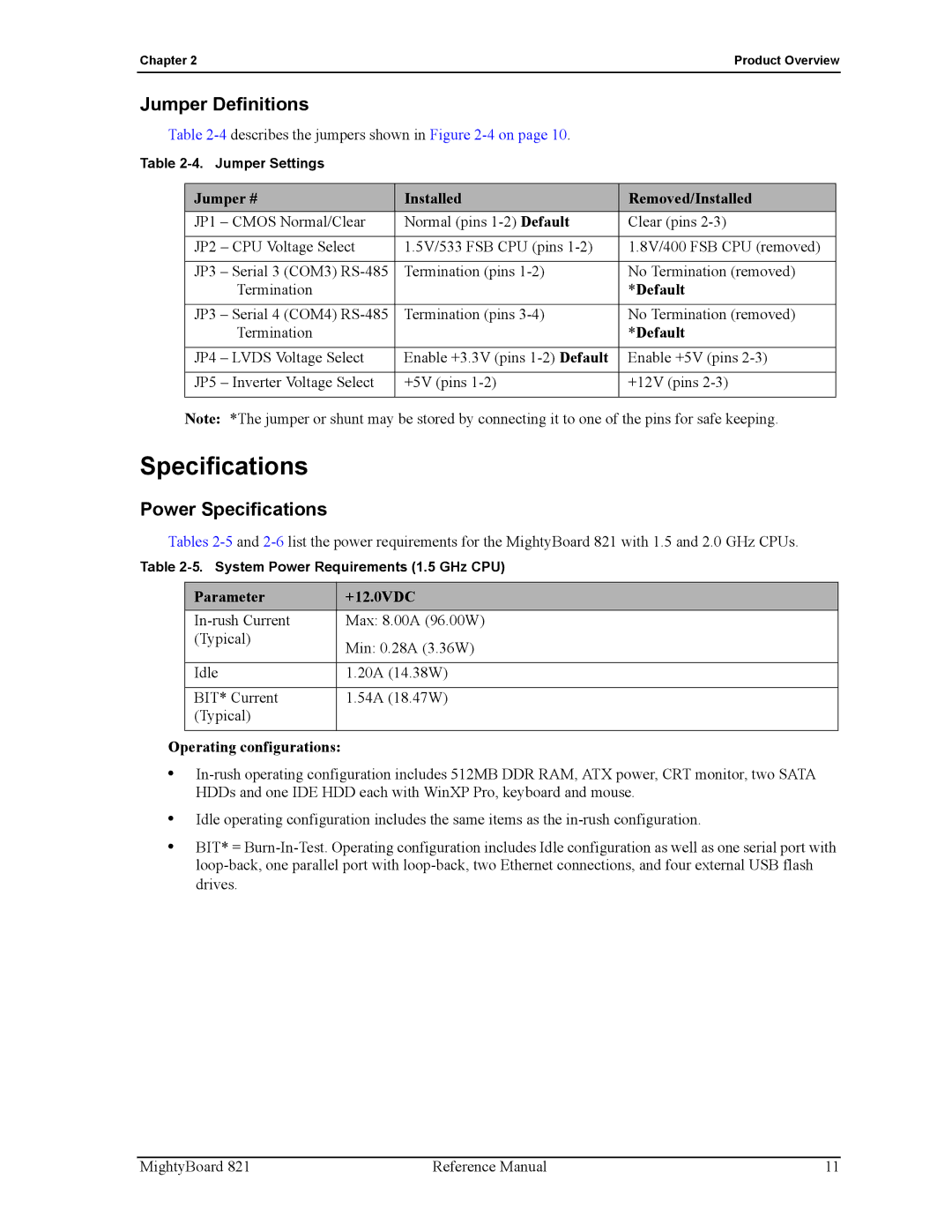
Table
Table
Jumper # | Installed | Removed/Installed |
JP1 – CMOS Normal/Clear | Normal (pins | Clear (pins |
|
|
|
JP2 – CPU Voltage Select | 1.5V/533 FSB CPU (pins | 1.8V/400 FSB CPU (removed) |
|
|
|
JP3 – Serial 3 (COM3) | Termination (pins | No Termination (removed) |
Termination |
| *Default |
|
|
|
JP3 – Serial 4 (COM4) | Termination (pins | No Termination (removed) |
Termination |
| *Default |
|
|
|
JP4 – LVDS Voltage Select | Enable +3.3V (pins | Enable +5V (pins |
|
|
|
JP5 – Inverter Voltage Select | +5V (pins | +12V (pins |
|
|
|
Note: *The jumper or shunt may be stored by connecting it to one of the pins for safe keeping.
Specifications
Power Specifications
Tables
Table
Parameter | +12.0VDC |
Max: 8.00A (96.00W) | |
(Typical) | Min: 0.28A (3.36W) |
| |
|
|
Idle | 1.20A (14.38W) |
|
|
BIT* Current | 1.54A (18.47W) |
(Typical) |
|
|
|
Operating configurations:
•
•Idle operating configuration includes the same items as the
•BIT* =
MightyBoard 821 | Reference Manual | 11 |
