Chapter 3Hardware
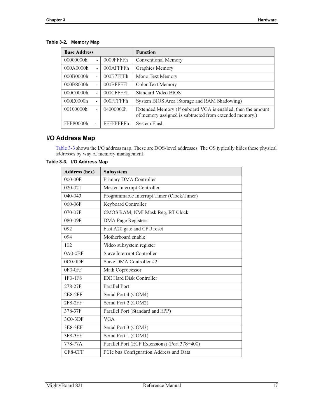
Table
Base Address |
|
| Function |
00000000h | - | 0009FFFFh | Conventional Memory |
|
|
|
|
000A0000h | - | 000AFFFFh | Graphics Memory |
|
|
|
|
000B0000h | - | 000B7FFFh | Mono Text Memory |
|
|
|
|
000B8000h | - | 000BFFFFh | Color Text Memory |
|
|
|
|
000C0000h | - | 000CFFFFh | Standard Video BIOS |
|
|
|
|
000E0000h | - | 000FFFFFh | System BIOS Area (Storage and RAM Shadowing) |
|
|
|
|
00100000h | - | 04000000h | Extended Memory (If onboard VGA is enabled, then the amount |
|
|
| of memory assigned is subtracted from extended memory.) |
|
|
|
|
FFF80000h | - | FFFFFFFFh | System Flash |
|
|
|
|
I/O Address Map
Table
Table
Address (hex) | Subsystem |
Primary DMA Controller | |
|
|
Master Interrupt Controller | |
|
|
Programmable Interrupt Timer (Clock/Timer) | |
|
|
Keyboard Controller | |
|
|
CMOS RAM, NMI Mask Reg, RT Clock | |
|
|
DMA Page Registers | |
|
|
092 | Fast A20 gate and CPU reset |
|
|
094 | Motherboard enable |
|
|
102 | Video subsystem register |
|
|
Slave Interrupt Controller | |
|
|
Slave DMA Controller #2 | |
|
|
Math Coprocessor | |
|
|
IDE Hard Disk Controller | |
|
|
Parallel Port | |
|
|
Serial Port 4 (COM4) | |
|
|
Serial Port 2 (COM2) | |
|
|
Parallel Port (Standard and EPP) | |
|
|
VGA | |
|
|
Serial Port 3 (COM3) | |
|
|
Serial Port 1 (COM1) | |
|
|
Parallel Port (ECP Extensions) (Port 378+400) | |
|
|
| PCIe bus Configuration Address and Data |
|
|
MightyBoard 821 | Reference Manual | 17 |
