Chapter 2 | Product Overview |
J17
J18
DIMM2 | DIMM1 |
J16
J15
JP6
F2
J9 J6
J4
J8
J5
J20
J21
J2
J3
F1![]()
J1
J22 JP1 BT1
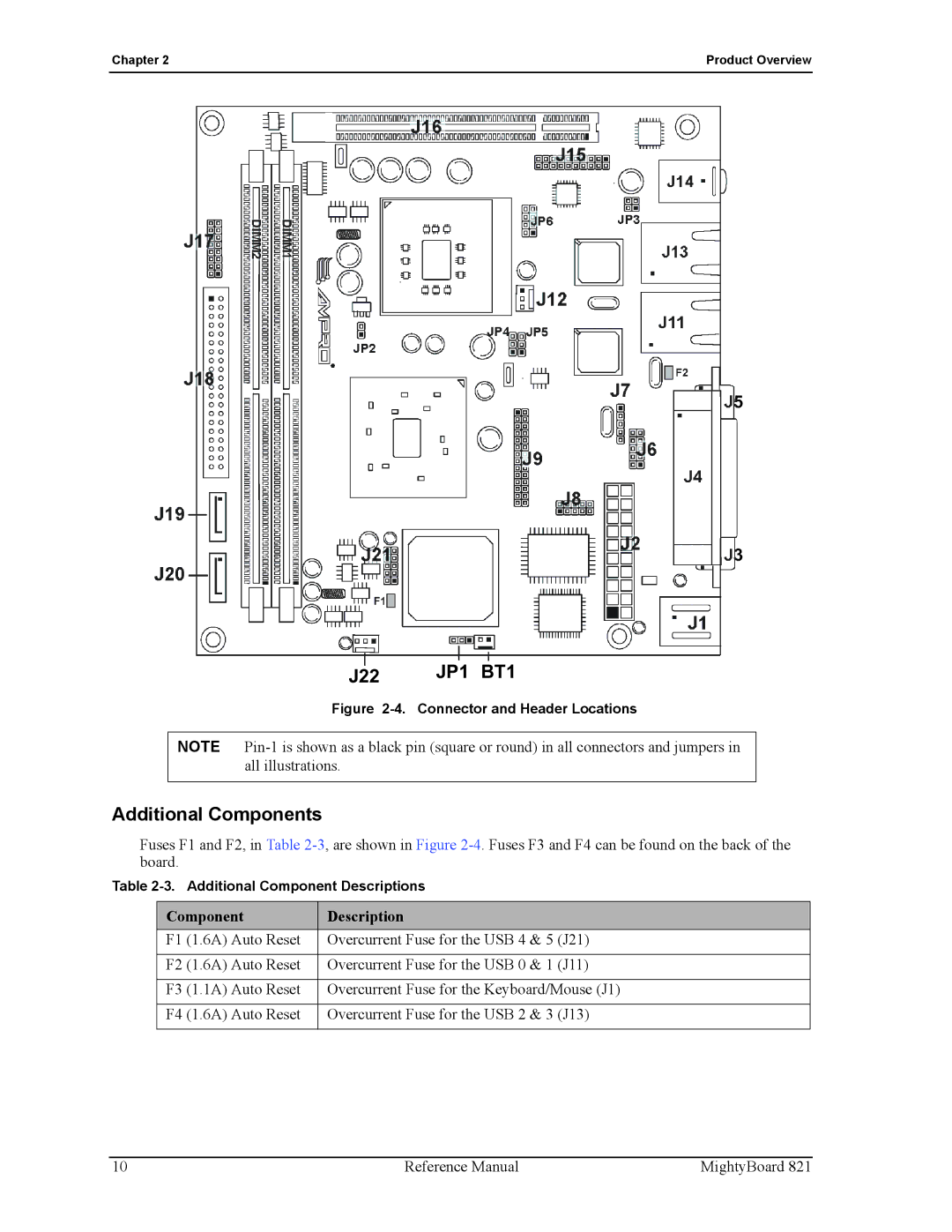
Figure 2-4. Connector and Header Locations
NOTE
Additional Components
Fuses F1 and F2, in Table
Table
Component | Description |
F1 (1.6A) Auto Reset | Overcurrent Fuse for the USB 4 & 5 (J21) |
|
|
F2 (1.6A) Auto Reset | Overcurrent Fuse for the USB 0 & 1 (J11) |
|
|
F3 (1.1A) Auto Reset | Overcurrent Fuse for the Keyboard/Mouse (J1) |
|
|
F4 (1.6A) Auto Reset | Overcurrent Fuse for the USB 2 & 3 (J13) |
|
|
10 | Reference Manual | MightyBoard 821 |