Chapter 3


Hardware


Pin #

Signal

Description


47

AD15

Address/Data bus 15 – Refer to pin-23 for more information.


48

ASGND

Analog Ground – This ground is used for the sound controller and an


external amplifier to achieved the lowest audio noise levels.


49

CBE1*

Bus Command and Byte Enable 1 – Refer to pin-31 for more information.


50

AOUT_R

Stereo Line Output Right channel – This output signal has a nominal level of


1 volt RMS into 10k impedance load. This output signal can not drive low-


impedance speakers directly


51

VCC2

+5 volts +/-%5


52

VCC3

+5 volts +/-%5


53

PAR

PCI bus Parity bit – This signal is the even parity bit on AD[31:0] and


CBE[3:0]*.


54

SERR*

System Error – This signal is for reporting address parity errors.


55

PERR*

Parity Error – This signal is driven by the PCI target during a write to


indicate a data parity error has been detected.


56

RESERVED

Reserved


57

PME*

Power Management Event – This signal is an optional signal that can be


used by a device to request a change in the device or system power state.


58

USB2-

Universal Serial Bus Port 2 Data Negative Polarity


59

LOCK*

Lock – This signal indicates an operation that may require multiple


transactions to complete.


60

DEVSEL*

Device Select – This signal is driven by the target device when its address is


decoded.


61

TRDY*

Target Ready – This signal indicates the selected device’s ability to


complete the current cycle of transaction. Both IRDY* and TRDY* must be


asserted to terminate a data cycle.


62

USB3-

Universal Serial Bus Port 3 Data Negative Polarity


63

IRDY*

Initiator Ready – This signal indicates the master’s ability to complete the


current data cycle of the transaction.


64

STOP*

Stop – This signal is driven by the current PCI target to request the master to


stop the current transaction.


65

FRAME*

PCI bus Frame access – This signal is driven by the current master to


indicate the start of a transaction and will remain active until the final data


cycle.


66

USB2+

Universal Serial Bus Port 2 Data Positive Polarity


67

GND

Ground


68

GND

Ground


69

AD16

Address/Data bus 16 – Refer to pin-23 for more information.


70

CBE2*

Bus Command and Byte Enable 2 – Refer to pin-31 for more information.


71

AD17

Address/Data bus 17 – Refer to pin-23 for more information.


72

USB3+

Universal Serial Bus Port 3 Data Positive Polarity


73

AD19

Address/Data bus 19 – Refer to pin-23 for more information.


74

AD18

Address/Data bus 18 – Refer to pin-23 for more information.


75

AD20

Address/Data bus 20 – Refer to pin-23 for more information.


XTX 820

Reference Manual

27

Page 33
Image 33
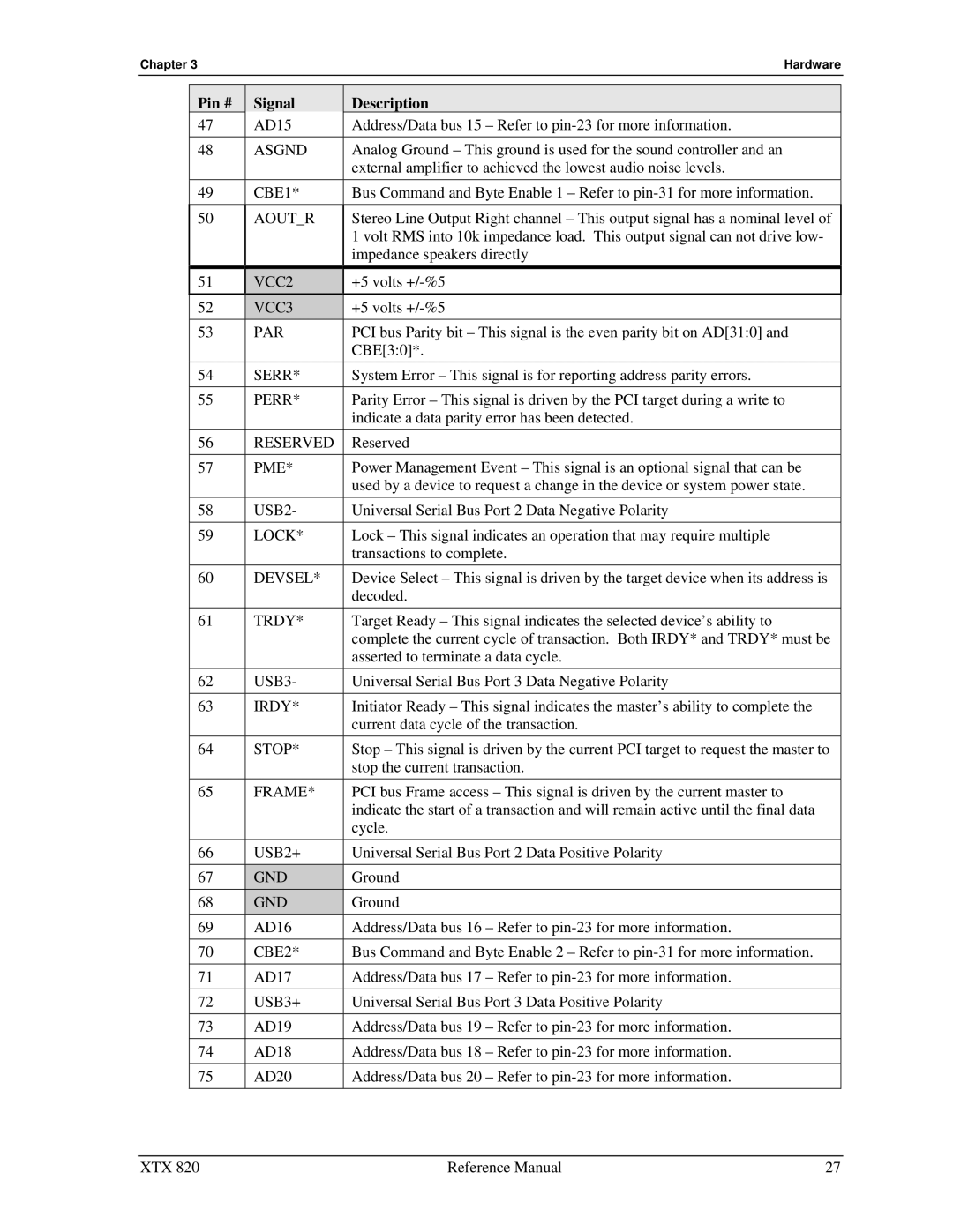
Ampro Corporation XTX 820 manual Aoutr, VCC2, VCC3, Reserved

XTX 820 specifications

Ampro Corporation has made a significant mark in the world of embedded systems with its versatile XTX 820 embedded computing module. The XTX 820 is designed to cater to a wide array of applications, ranging from industrial automation to medical devices, providing developers with a powerful yet compact solution.

One of the standout features of the XTX 820 is its advanced processing capabilities. The module is equipped with an Intel Atom processor, which delivers impressive performance while operating at low power levels. This combination makes the XTX 820 suitable for environments where energy efficiency is essential. The Atom processor allows for seamless multitasking and support for demanding applications without compromising on thermal efficiency.

In terms of memory, the XTX 820 supports a range of configurations, accommodating both DDR2 and DDR3 memory types. With a maximum of up to 4GB of onboard memory, this module ensures that applications can run smoothly and efficiently across various tasks. The flexibility in memory options enables developers to tailor their designs according to specific project needs.

Connectivity is another strong suit of the XTX 820. The module comes with multiple I/O interfaces that enhance its utility in various applications. It features USB, Serial, and Parallel ports, along with support for LVDS display and audio interfaces. This diverse range of connectivity options allows the XTX 820 to integrate easily with a variety of systems and devices, facilitating seamless data transfer and communication.

Security is increasingly critical in embedded systems, and Ampro has integrated robust security features into the XTX 820. This includes support for hardware-based security solutions, which can protect sensitive data and prevent unauthorized access. Such characteristics make the module a suitable choice for industries where data integrity is paramount.

Furthermore, the XTX 820 boasts an impressive range of environmental operating conditions. It is designed to function in extreme temperatures, making it suitable for outdoor and industrial applications where fluctuations in temperature can be a concern.

In conclusion, the Ampro Corporation XTX 820 embedded computing module emerges as a versatile platform that combines performance, memory flexibility, robust connectivity, and enhanced security features. Its design is tailored to meet the demands of various industries, making it a reliable choice for developers looking for advanced embedded solutions.