XTX 820 specifications
Ampro Corporation has made a significant mark in the world of embedded systems with its versatile XTX 820 embedded computing module. The XTX 820 is designed to cater to a wide array of applications, ranging from industrial automation to medical devices, providing developers with a powerful yet compact solution.One of the standout features of the XTX 820 is its advanced processing capabilities. The module is equipped with an Intel Atom processor, which delivers impressive performance while operating at low power levels. This combination makes the XTX 820 suitable for environments where energy efficiency is essential. The Atom processor allows for seamless multitasking and support for demanding applications without compromising on thermal efficiency.
In terms of memory, the XTX 820 supports a range of configurations, accommodating both DDR2 and DDR3 memory types. With a maximum of up to 4GB of onboard memory, this module ensures that applications can run smoothly and efficiently across various tasks. The flexibility in memory options enables developers to tailor their designs according to specific project needs.
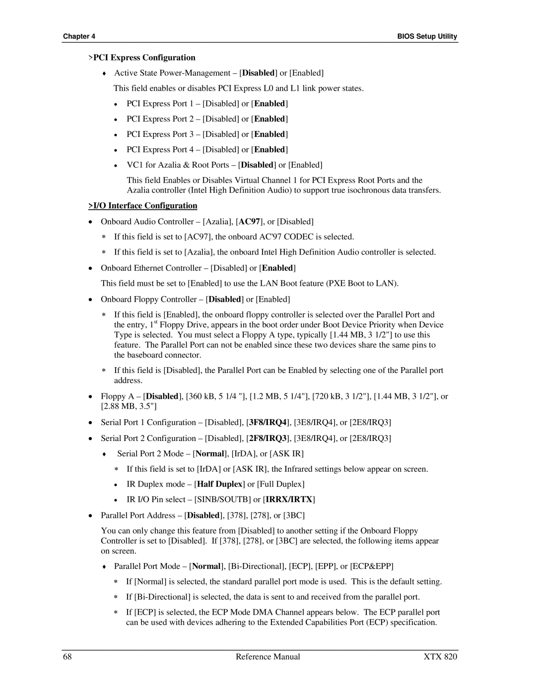
Connectivity is another strong suit of the XTX 820. The module comes with multiple I/O interfaces that enhance its utility in various applications. It features USB, Serial, and Parallel ports, along with support for LVDS display and audio interfaces. This diverse range of connectivity options allows the XTX 820 to integrate easily with a variety of systems and devices, facilitating seamless data transfer and communication.
Security is increasingly critical in embedded systems, and Ampro has integrated robust security features into the XTX 820. This includes support for hardware-based security solutions, which can protect sensitive data and prevent unauthorized access. Such characteristics make the module a suitable choice for industries where data integrity is paramount.
Furthermore, the XTX 820 boasts an impressive range of environmental operating conditions. It is designed to function in extreme temperatures, making it suitable for outdoor and industrial applications where fluctuations in temperature can be a concern.
In conclusion, the Ampro Corporation XTX 820 embedded computing module emerges as a versatile platform that combines performance, memory flexibility, robust connectivity, and enhanced security features. Its design is tailored to meet the demands of various industries, making it a reliable choice for developers looking for advanced embedded solutions.
