Pass-Through Configurations
This method allows IR signals generated from hand-held remotes to easily
pass through the opaque red shell/cover. The internal IR LED can be
oriented to either face towards or away from the shell (Figure 1),
depending on its output configuration. Use the low-output configuration
when device is being saturated by an IR signal. Use the high-output
configuration when the device isn’t receiving enough of an IR signal and
requires more strength. The side with the round “bump” is the high-output
side.
CC-IRC IR Emitter Overview
The IR Emitter adheres directly to the IR control window of your
equipment by using clear two-sided tape to securely adhere the opaque
shield. This “standard configuration” allows you to control your equipment
either from either IR emitters or a hand-held remote control.
The two black adhesive-backed window shields (Figure 3) are included
within each emitter package and allow for alternate configurations. With
this shield (surrounding the internal emitter), you can restrict IR reception
through the device’s control window by blocking any interference or IR
signals produced by sources other than the internal emitter. Without this
shield, any incoming IR signal can pass through to the IR control window
and overlap signals sent via the emitter (Figure 1).
Note: Each CC-IRC package is shipped with four sealed alcohol pads
which can be used to clean any adhesive residue left from a previous
installation of the window shield on the surface of a device’s IR
control window.
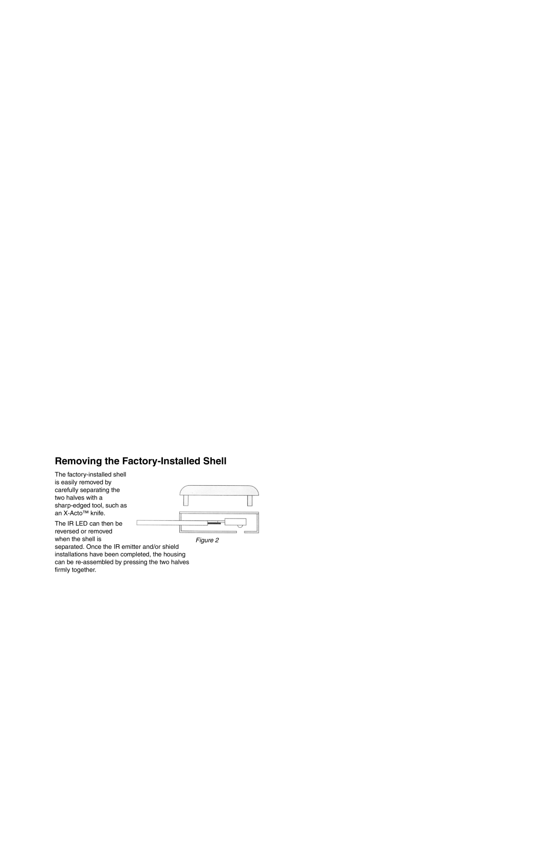
Removing the Factory-Installed Shell
The factory-installed shell
is easily removed by
carefully separating the
two halves with a
sharp-edged tool, such as
an X-Acto™ knife.
The IR LED can then be
reversed or removed
when the shell is
separated. Once the IR emitter and/or shield
installations have been completed, the housing
can be re-assembled by pressing the two halves
firmly together.
Shielded Configuration
Use this configuration to prevent interference from fluorescent lights or
other IR sources. The metallic shield prohibits passage of external IR
signals and ensures proper IR signals will be received from the emitter.
1. Remove the IR LED from the factory-installed shell (Figure 2).
2. Test fit the location and size of the IR shield (Figure 3) on the target
device. If necessary, use scissors to trim the shield to fit the opening
of the IR window.
3. Remove the adhesive backing from the IR shield and carefully place
the IR LED into the recessed area using the correct orientation
(Figure 1). Make sure the wires attached to the IR LED are not
shorted together.
4. Flip the shield-emitter combo back over and begin to carefully position
the shield over the IR control window so that it covers the entire
surface (Figure 4). This keeps any other signal from coming through.
5. Press firmly on the shield surface to activate the pressure-sensitive
adhesive.
Low-Output High-Output
Figure 2
Opaque IR Window Shield
Figure 3
Pass-Through Configurations
This method allows IR signals generated from hand-held remotes to easily
pass through the opaque red shell/cover. The internal IR LED can be
oriented to either face towards or away from the shell (Figure 1),
depending on its output configuration. Use the low-output configuration
when device is being saturated by an IR signal. Use the high-output
configuration when the device isn’t receiving enough of an IR signal and
requires more strength. The side with the round “bump” is the high-output
side.
CC-IRC IR Emitter Overview
The IR Emitter adheres directly to the IR control window of your
equipment by using clear two-sided tape to securely adhere the opaque
shield. This “standard configuration” allows you to control your equipment
either from either IR emitters or a hand-held remote control.
The two black adhesive-backed window shields (Figure 3) are included
within each emitter package and allow for alternate configurations. With
this shield (surrounding the internal emitter), you can restrict IR reception
through the device’s control window by blocking any interference or IR
signals produced by sources other than the internal emitter. Without this
shield, any incoming IR signal can pass through to the IR control window
and overlap signals sent via the emitter (Figure 1).
Note: Each CC-IRC package is shipped with four sealed alcohol pads
which can be used to clean any adhesive residue left from a previous
installation of the window shield on the surface of a device’s IR
control window.
Shielded Configuration
Use this configuration to prevent interference from fluorescent lights or
other IR sources. The metallic shield prohibits passage of external IR
signals and ensures proper IR signals will be received from the emitter.
1. Remove the IR LED from the factory-installed shell (Figure 2).
2. Test fit the location and size of the IR shield (Figure 3) on the target
device. If necessary, use scissors to trim the shield to fit the opening
of the IR window.
3. Remove the adhesive backing from the IR shield and carefully place
the IR LED into the recessed area using the correct orientation
(Figure 1). Make sure the wires attached to the IR LED are not
shorted together.
4. Flip the shield-emitter combo back over and begin to carefully position
the shield over the IR control window so that it covers the entire
surface (Figure 4). This keeps any other signal from coming through.
5. Press firmly on the shield surface to activate the pressure-sensitive
adhesive.
Figure 1
Away from
IR window
Towar ds
IR window
Adhesive
Low-Output High-Output
Figure 1
Away from
IR window
Towar ds
IR window
Adhesive
Removing the Factory-Installed Shell
The factory-installed shell
is easily removed by
carefully separating the
two halves with a
sharp-edged tool, such as
an X-Acto™ knife.
The IR LED can then be
reversed or removed
when the shell is
separated. Once the IR emitter and/or shield
installations have been completed, the housing
can be re-assembled by pressing the two halves
firmly together.
Figure 2
Opaque IR Window Shield
Figure 3