FIREPLACE INSTALLATION

Installing Optional Blower Accessories (Cont.)

17

FIREPLACE INSTALLATION

Continued

5.Mount speed control box to switch bracket by placing the plastic control shaft forward through the round opening in the switch bracket (see Figure 26).

6.While supporting speed control, secure control shaft with lock nut by pushing and turning lock nut with pliers clockwise until it is tight against front panel. Place control knob provided on shaft.

7.Turn on power to duplex outlet if previously turned off per the warning in column 2, page 16.

8.Plug in blower power cord.

a.If your firebox is installed as a freestanding unit with an accessory mantel, determine whether the power cord will exit the left side or the right side of the firebox. Route power cord through exit hole and plug the power cord into a wall receptacle near the firebox.

b.If your firebox installation is recessed and/or pre-wired, plug the power cord into the duplex outlet provided. Refer to your firebox ownerʼs manual for instructions on wiring the duplex outlet.

CAUTION: Never touch the blower wheel while in operation.

9.

Check to make sure that the power cord is completely clear of the


blower wheel and that there are no other foreign objects in blower


wheel. Turn blower on and check for operation. Turn blower off


by turning knob fully counterclockwise before continuing.

Model BKT Installation

Note: When installing the BKT thermostatically-controlled blower, you must first secure the thermal switch bracket to the blower if it has not already been factory installed.

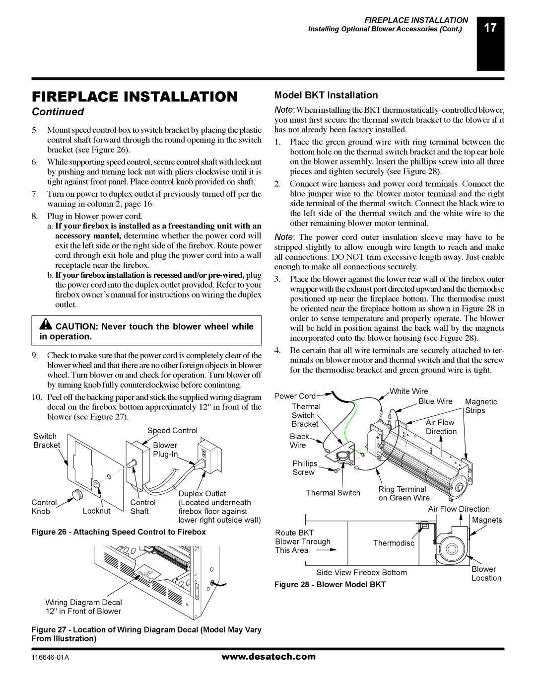
1.Place the green ground wire with ring terminal between the bottom hole on the thermal switch bracket and the top ear hole on the blower assembly. Insert the phillips screw into all three pieces and tighten securely (see Figure 28).

2.Connect wire harness and power cord terminals. Connect the blue jumper wire to the blower motor terminal and the right side terminal of the thermal switch. Connect the black wire to the left side of the thermal switch and the white wire to the other remaining blower motor terminal.

Note: The power cord outer insulation sleeve may have to be stripped slightly to allow enough wire length to reach and make all connections. DO NOT trim excessive length away. Just enable enough to make all connections securely.

3.Place the blower against the lower rear wall of the firebox outer wrapper with the exhaust port directed upward and the thermodisc positioned up near the fireplace bottom. The thermodisc must be oriented near the fireplace bottom as shown in Figure 28 in order to sense temperature and properly operate. The blower will be held in position against the back wall by the magnets incorporated onto the blower housing (see Figure 28).

4.Be certain that all wire terminals are securely attached to ter- minals on blower motor and thermal switch and that the screw for the thermodisc bracket and green ground wire is tight.

10. Peel off the backing paper and stick the supplied wiring diagram

decal on the firebox bottom approximately 12" in front of the

blower (see Figure 27).

Switch

Speed Control


Bracket

Blower


Plug-In


Control

Duplex Outlet

Control

(Located underneath

Power Cord

Thermal

Switch

Bracket

Black

Wire

Phillips Screw

Thermal Switch

White Wire


Blue Wire

Magnetic


Strips

Air Flow


Direction


Ring Terminal on Green Wire

Knob

Locknut

Shaft

firebox floor against


lower right outside wall)

Figure 26 - Attaching Speed Control to Firebox

Wiring Diagram Decal

12" in Front of Blower

Figure 27 - Location of Wiring Diagram Decal (Model May Vary From Illustration)

Route BKT


Blower Through

Thermodisc

This Area


Side View Firebox Bottom

Figure 28 - Blower Model BKT

Air Flow Direction Magnets

Blower

Location

116646-01A

www.desatech.com

Page 17
Image 17
Desa CGDV32NR, (V)T32N-A Series, (V)T32P-A Series installation manual Model BKT Installation, Blower see Figure

CGDV32NR, (V)T32N-A Series, (V)T32P-A Series specifications

The Desa (V)T32N-A Series and (V)T32P-A Series, along with the CGDV32NR, represent a significant advancement in modern energy solutions, combining efficiency, durability, and innovative technologies to meet the evolving needs of consumers and businesses alike.

The (V)T32N-A Series is designed specifically for residential applications, featuring a compact and lightweight structure that enables easy installation in various settings. Its primary characteristic is its energy-efficient operation, which minimizes energy consumption while providing optimal heating performance. This series incorporates advanced heating technology, delivering uniform warmth and maximizing comfort in living spaces. The user-friendly digital control panel offers a range of settings, allowing users to customize their heating preferences with ease.

In contrast, the (V)T32P-A Series is tailored for commercial use, boasting a robust design that can withstand the demands of high-traffic environments. This series features enhanced output capacity and quicker heating response times, making it suitable for large venues such as offices, retail spaces, and warehouses. The Duracore technology employed in this series ensures that the heating system is not only powerful but also reliable, reducing downtime and maintenance costs.

The CGDV32NR offers a versatile solution that excels in both residential and commercial applications. Its standout feature is the dual-fuel capability, allowing users to choose between natural gas and propane. This flexibility provides an additional layer of convenience and adaptability, catering to diverse energy needs and preferences. Furthermore, the CGDV32NR is equipped with smart technology that integrates with home automation systems, enabling users to control their heating from a mobile device or smart home interface.

All three series incorporate safety features such as flame failure shut-off and overheat protection, ensuring peace of mind for users. The sleek designs and aesthetic options of the (V)T32N-A and (V)T32P-A Series allow them to blend seamlessly with various interior styles, while the CGDV32NR’s practical functionality and modern design make it an attractive option for any setting.

In summary, the Desa (V)T32N-A Series, (V)T32P-A Series, and CGDV32NR combine cutting-edge technology, energy efficiency, and user-friendly features to deliver ideal solutions for heating needs across residential and commercial landscapes. These series showcase Desa's commitment to innovation, sustainability, and customer satisfaction, marking a significant step forward in heating technology.