8

VENTING INSTALLATION INSTRUCTIONS

Installation Planning

VENTING INSTALLATION INSTRUCTIONS

Continued

INSTALLATION PLANNING

There are two basic types of direct-vent installation:

Horizontal Termination

Vertical Termination

Horizontal Termination Installation

Female

Locking

Lugs

Male Slots

IMPORTANT: Horizontal square terminations require only inner portion of wall firestop. Horizontal installations using round ter- mination require exterior portion of wall firestop available only in vent kit HTK (see Figure 14, page 10).

1.Set the fireplace in its desired location and determine the route your horizontal venting will take. Do not secure the fireplace until all venting has been installed. Some installations require sliding the fireplace in and out of position to make final venting connections. Figures 14 through 18 on pages 10 through 12 show different configurations for venting with horizontal termination that will help you decide which application best suits your instal- lation. Check to see if wall studs or roof rafters are in the path of your desired venting route. If they are, you may want to adjust the location of the fireplace.

2.Direct vent pipe sections and components are designed with special twist-lock connections.

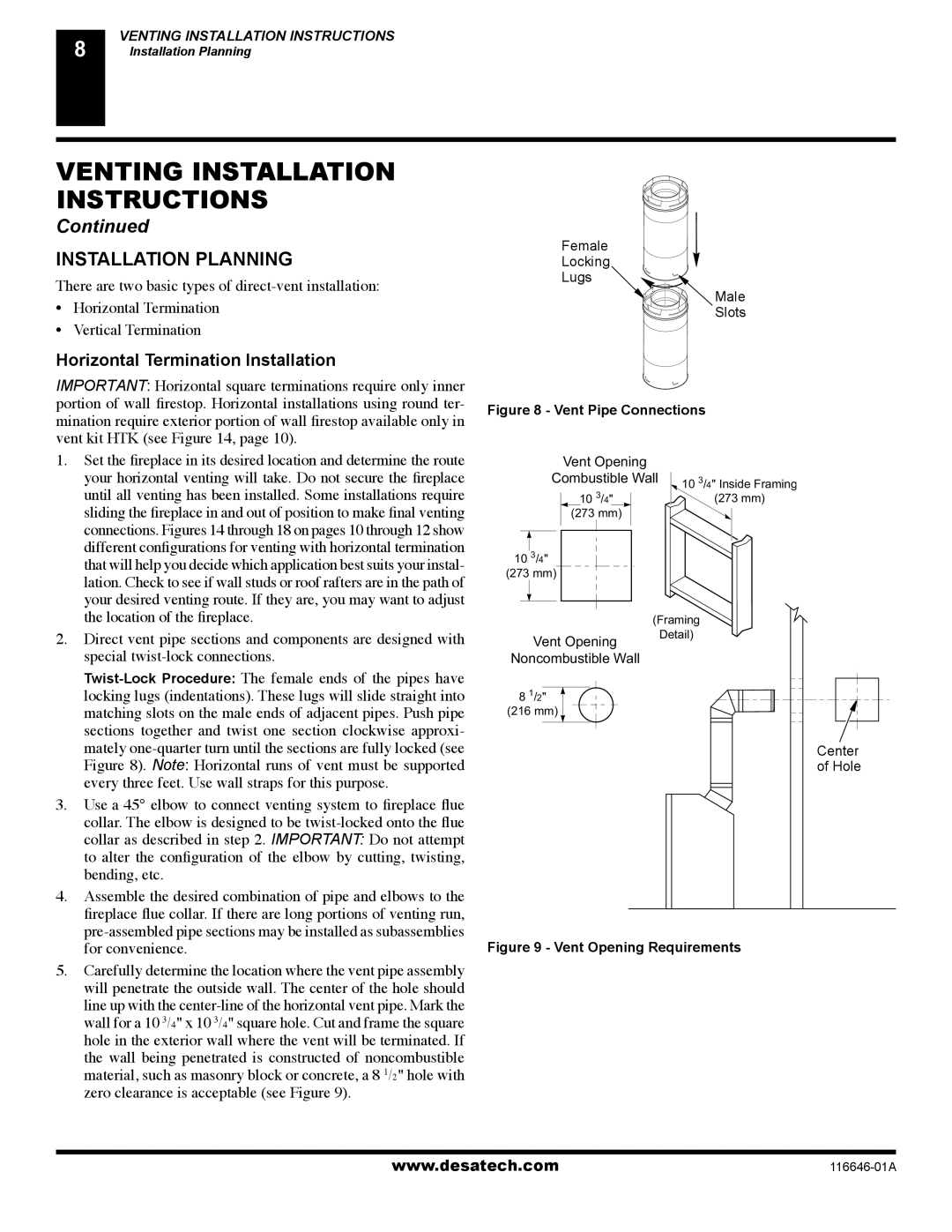
Twist-Lock Procedure: The female ends of the pipes have locking lugs (indentations). These lugs will slide straight into matching slots on the male ends of adjacent pipes. Push pipe sections together and twist one section clockwise approxi- mately one-quarter turn until the sections are fully locked (see Figure 8). Note: Horizontal runs of vent must be supported every three feet. Use wall straps for this purpose.

3.Use a 45° elbow to connect venting system to fireplace flue collar. The elbow is designed to be twist-locked onto the flue collar as described in step 2. IMPORTANT: Do not attempt to alter the configuration of the elbow by cutting, twisting, bending, etc.

4.Assemble the desired combination of pipe and elbows to the fireplace flue collar. If there are long portions of venting run, pre-assembled pipe sections may be installed as subassemblies for convenience.

5.Carefully determine the location where the vent pipe assembly will penetrate the outside wall. The center of the hole should line up with the center-line of the horizontal vent pipe. Mark the wall for a 10 3/4" x 10 3/4" square hole. Cut and frame the square hole in the exterior wall where the vent will be terminated. If the wall being penetrated is constructed of noncombustible material, such as masonry block or concrete, a 8 1/2" hole with zero clearance is acceptable (see Figure 9).

Figure 8 - Vent Pipe Connections


Vent Opening


Combustible Wall

10

3

/4" Inside Framing


3


10

/4"


(273 mm)


(273 mm)


10

3

/4"


(273 mm)


(Framing


Vent Opening


Detail)


Noncombustible Wall


8

1

/2"


(216 mm)


Center

of Hole

Figure 9 - Vent Opening Requirements

www.desatech.com

116646-01A

Page 8
Image 8
Desa CGDV32NR, (V)T32N-A Series, (V)T32P-A Series Installation Planning, Horizontal Termination Installation

CGDV32NR, (V)T32N-A Series, (V)T32P-A Series specifications

The Desa (V)T32N-A Series and (V)T32P-A Series, along with the CGDV32NR, represent a significant advancement in modern energy solutions, combining efficiency, durability, and innovative technologies to meet the evolving needs of consumers and businesses alike.

The (V)T32N-A Series is designed specifically for residential applications, featuring a compact and lightweight structure that enables easy installation in various settings. Its primary characteristic is its energy-efficient operation, which minimizes energy consumption while providing optimal heating performance. This series incorporates advanced heating technology, delivering uniform warmth and maximizing comfort in living spaces. The user-friendly digital control panel offers a range of settings, allowing users to customize their heating preferences with ease.

In contrast, the (V)T32P-A Series is tailored for commercial use, boasting a robust design that can withstand the demands of high-traffic environments. This series features enhanced output capacity and quicker heating response times, making it suitable for large venues such as offices, retail spaces, and warehouses. The Duracore technology employed in this series ensures that the heating system is not only powerful but also reliable, reducing downtime and maintenance costs.

The CGDV32NR offers a versatile solution that excels in both residential and commercial applications. Its standout feature is the dual-fuel capability, allowing users to choose between natural gas and propane. This flexibility provides an additional layer of convenience and adaptability, catering to diverse energy needs and preferences. Furthermore, the CGDV32NR is equipped with smart technology that integrates with home automation systems, enabling users to control their heating from a mobile device or smart home interface.

All three series incorporate safety features such as flame failure shut-off and overheat protection, ensuring peace of mind for users. The sleek designs and aesthetic options of the (V)T32N-A and (V)T32P-A Series allow them to blend seamlessly with various interior styles, while the CGDV32NR’s practical functionality and modern design make it an attractive option for any setting.

In summary, the Desa (V)T32N-A Series, (V)T32P-A Series, and CGDV32NR combine cutting-edge technology, energy efficiency, and user-friendly features to deliver ideal solutions for heating needs across residential and commercial landscapes. These series showcase Desa's commitment to innovation, sustainability, and customer satisfaction, marking a significant step forward in heating technology.