6

LOCATION OF TERMINATION CAP

LOCATION OF TERMINATION CAP

D

E V

B L


C


Fixed


V


Closed


F


V


Openable


B

B

B

Openable Fixed Closed

H

V

B

I

V J XG

AM

NN


G


V


G

V K X

V


A

V TERMINATION CAP

X AIR SUPPLY INLET

G GAS METER

RESTRICTED AREA (TERMINATION PROHIBITED)

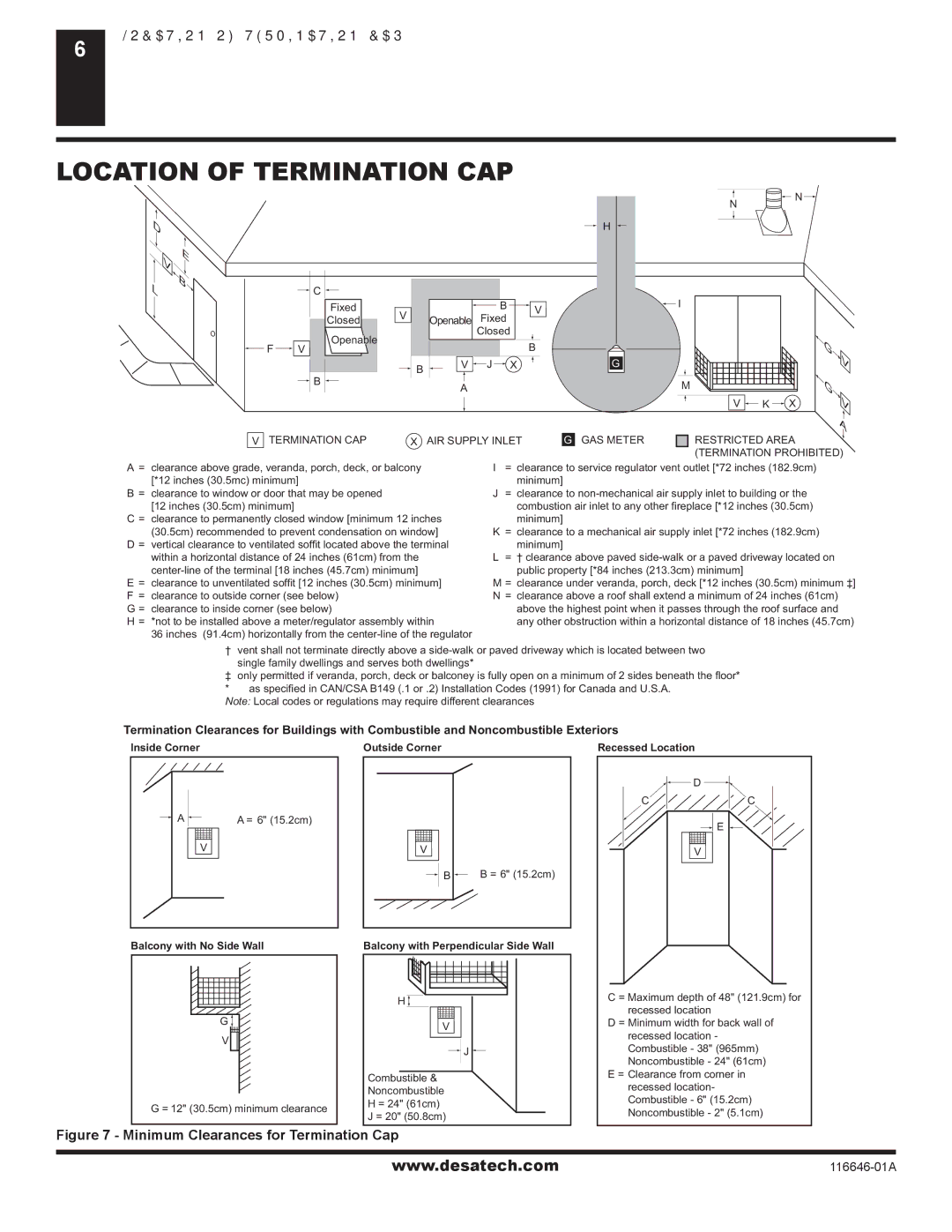
A= clearance above grade, veranda, porch, deck, or balcony [*12 inches (30.5mc) minimum]

B= clearance to window or door that may be opened [12 inches (30.5cm) minimum]

C = clearance to permanently closed window [minimum 12 inches (30.5cm) recommended to prevent condensation on window]

D = vertical clearance to ventilated soffit located above the terminal within a horizontal distance of 24 inches (61cm) from the center-line of the terminal [18 inches (45.7cm) minimum]

E= clearance to unventilated soffit [12 inches (30.5cm) minimum] F = clearance to outside corner (see below)

G = clearance to inside corner (see below)

H = *not to be installed above a meter/regulator assembly within

36 inches (91.4cm) horizontally from the center-line of the regulator

I= clearance to service regulator vent outlet [*72 inches (182.9cm) minimum]

J= clearance to non-mechanical air supply inlet to building or the combustion air inlet to any other fireplace [*12 inches (30.5cm)

minimum]

K= clearance to a mechanical air supply inlet [*72 inches (182.9cm) minimum]

L= † clearance above paved side-walk or a paved driveway located on public property [*84 inches (213.3cm) minimum]

M = clearance under veranda, porch, deck [*12 inches (30.5cm) minimum ‡]

N= clearance above a roof shall extend a minimum of 24 inches (61cm) above the highest point when it passes through the roof surface and any other obstruction within a horizontal distance of 18 inches (45.7cm)

† vent shall not terminate directly above a side-walk or paved driveway which is located between two single family dwellings and serves both dwellings*

only permitted if veranda, porch, deck or balconey is fully open on a minimum of 2 sides beneath the floor* * as specified in CAN/CSA B149 (.1 or .2) Installation Codes (1991) for Canada and U.S.A.

Note: Local codes or regulations may require different clearances

Termination Clearances for Buildings with Combustible and Noncombustible Exteriors

Inside Corner

Outside Corner

Recessed Location

AA = 6" (15.2cm)

V

Balcony with No Side Wall

G

V

G = 12" (30.5cm) minimum clearance

V

B B = 6" (15.2cm)

Balcony with Perpendicular Side Wall

H

V

J

Combustible &

Noncombustible

H = 24" (61cm)

J = 20" (50.8cm)


D

C

C

E

V

C = Maximum depth of 48" (121.9cm) for recessed location

D = Minimum width for back wall of recessed location - Combustible - 38" (965mm) Noncombustible - 24" (61cm)

E = Clearance from corner in recessed location- Combustible - 6" (15.2cm) Noncombustible - 2" (5.1cm)

Figure 7 - Minimum Clearances for Termination Cap

www.desatech.com

116646-01A

Page 6
Image 6
Desa (V)T32N-A Series, (V)T32P-A Series, CGDV32NR Location of Termination CAP, Termination CAP AIR Supply Inlet GAS Meter

CGDV32NR, (V)T32N-A Series, (V)T32P-A Series specifications

The Desa (V)T32N-A Series and (V)T32P-A Series, along with the CGDV32NR, represent a significant advancement in modern energy solutions, combining efficiency, durability, and innovative technologies to meet the evolving needs of consumers and businesses alike.

The (V)T32N-A Series is designed specifically for residential applications, featuring a compact and lightweight structure that enables easy installation in various settings. Its primary characteristic is its energy-efficient operation, which minimizes energy consumption while providing optimal heating performance. This series incorporates advanced heating technology, delivering uniform warmth and maximizing comfort in living spaces. The user-friendly digital control panel offers a range of settings, allowing users to customize their heating preferences with ease.

In contrast, the (V)T32P-A Series is tailored for commercial use, boasting a robust design that can withstand the demands of high-traffic environments. This series features enhanced output capacity and quicker heating response times, making it suitable for large venues such as offices, retail spaces, and warehouses. The Duracore technology employed in this series ensures that the heating system is not only powerful but also reliable, reducing downtime and maintenance costs.

The CGDV32NR offers a versatile solution that excels in both residential and commercial applications. Its standout feature is the dual-fuel capability, allowing users to choose between natural gas and propane. This flexibility provides an additional layer of convenience and adaptability, catering to diverse energy needs and preferences. Furthermore, the CGDV32NR is equipped with smart technology that integrates with home automation systems, enabling users to control their heating from a mobile device or smart home interface.

All three series incorporate safety features such as flame failure shut-off and overheat protection, ensuring peace of mind for users. The sleek designs and aesthetic options of the (V)T32N-A and (V)T32P-A Series allow them to blend seamlessly with various interior styles, while the CGDV32NR’s practical functionality and modern design make it an attractive option for any setting.

In summary, the Desa (V)T32N-A Series, (V)T32P-A Series, and CGDV32NR combine cutting-edge technology, energy efficiency, and user-friendly features to deliver ideal solutions for heating needs across residential and commercial landscapes. These series showcase Desa's commitment to innovation, sustainability, and customer satisfaction, marking a significant step forward in heating technology.