Quick Start Guide
IRX-SM+ Swivel-Mount Remote IR Sensor
Overview
The
Note: The
Note: The unit will not operate until JP1 is configured for either 38 kHz or 455 kHz.
•To receive 38 kHz, position the JP1 jumper on pins 1 and 2 (closer to the Phoenix connector).
•To receive 455 kHz (default setting), position the JP1 jumper on pins 2 and 3 (away from the Phoenix connector).
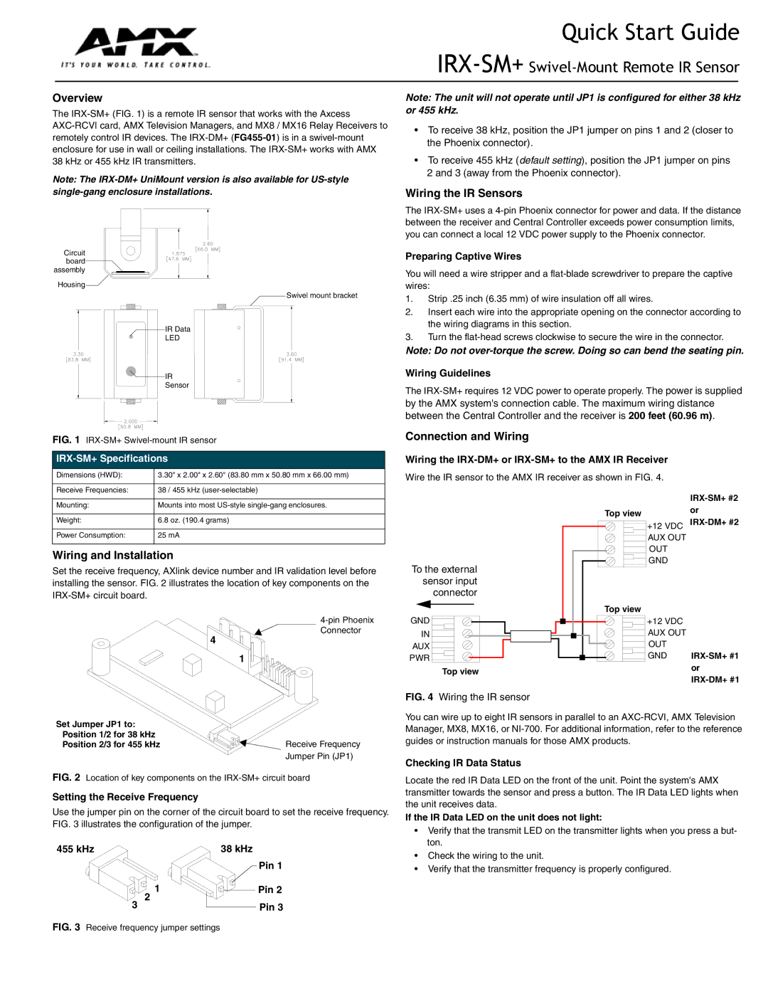
Circuit board assembly ![]()
![]()
Housing![]()
Swivel mount bracket
| IR Data | |
| LED | IR Sensor |
|
| |
| IR Data LED |
|
| IR |
|
| Sensor |
|
FIG. 1 | ||
|
| |
Dimensions (HWD): | 3.30" x 2.00" x 2.60" (83.80 mm x 50.80 mm x 66.00 mm) | |
Receive Frequencies: | 38 / 455 kHz | |
Wiring the IR Sensors
The
Preparing Captive Wires
You will need a wire stripper and a
1.Strip .25 inch (6.35 mm) of wire insulation off all wires.
2.Insert each wire into the appropriate opening on the connector according to the wiring diagrams in this section.
3.Turn the
Note: Do not
Wiring Guidelines
The
by the AMX system's connection cable. The maximum wiring distance between the Central Controller and the receiver is 200 feet (60.96 m).
Connection and Wiring
Wiring the IRX-DM+ or IRX-SM+ to the AMX IR Receiver
Wire the IR sensor to the AMX IR receiver as shown in FIG. 4.
Mounting: | Mounts into most |
|
|
Weight: | 6.8 oz. (190.4 grams) |
|
|
Power Consumption: | 25 mA |
Wiring and Installation
Set the receive frequency, AXlink device number and IR validation level before installing the sensor. FIG. 2 illustrates the location of key components on the
Connector
4
1
To the external sensor input connector
GND
IN
AUX
PWR
Top view
Top view
Top view |
+12 VDC AUX OUT OUT GND
+12 VDC AUX OUT OUT GND
Set Jumper JP1 to: |
|
Position 1/2 for 38 kHz | Receive Frequency |
Position 2/3 for 455 kHz | |
| Jumper Pin (JP1) |
FIG. 2 Location of key components on the IRX-SM+ circuit board
Setting the Receive Frequency
Use the jumper pin on the corner of the circuit board to set the receive frequency. FIG. 3 illustrates the configuration of the jumper.
455 kHz | 38 kHz |
| Pin 1 |
1 | Pin 2 |
2 |
|
3 | Pin 3 |
FIG. 3 Receive frequency jumper settings
FIG. 4 Wiring the IR sensor
You can wire up to eight IR sensors in parallel to an
Checking IR Data Status
Locate the red IR Data LED on the front of the unit. Point the system's AMX transmitter towards the sensor and press a button. The IR Data LED lights when the unit receives data.
If the IR Data LED on the unit does not light:
•Verify that the transmit LED on the transmitter lights when you press a but- ton.
•Check the wiring to the unit.
•Verify that the transmitter frequency is properly configured.