Product Information
Specifications
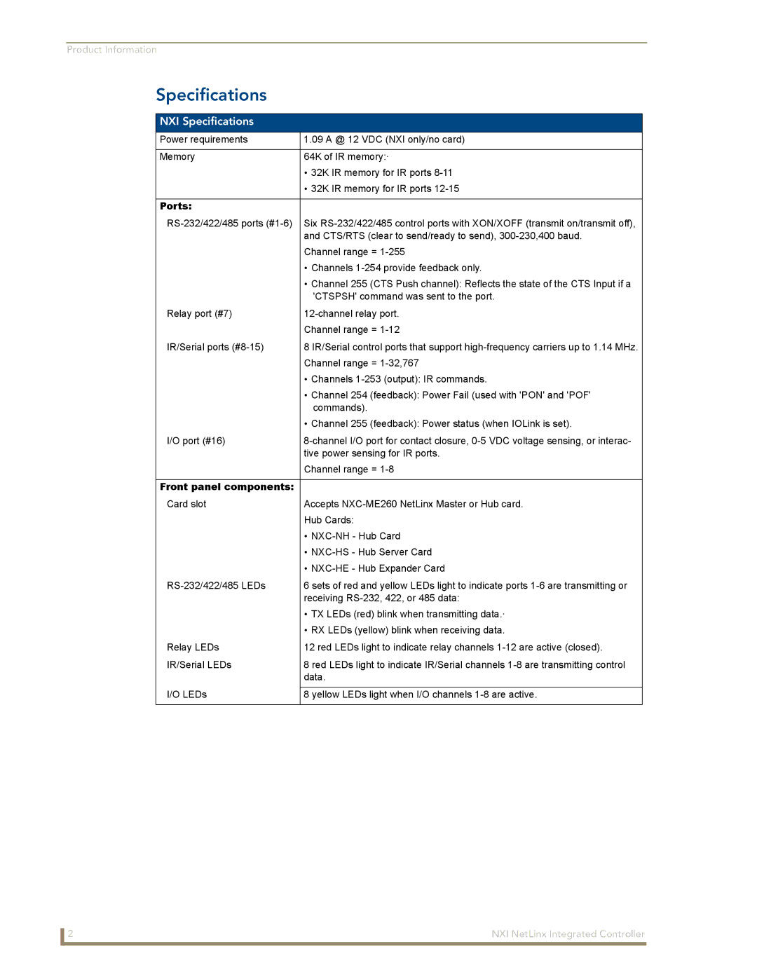
NXI Specifications
Power requirements | 1.09 A @ 12 VDC (NXI only/no card) |
|
|
Memory | 64K of IR memory:· |
| • 32K IR memory for IR ports |
| • 32K IR memory for IR ports |
|
|
Ports: |
|
Six | |
| and CTS/RTS (clear to send/ready to send), |
| Channel range = |
| • Channels |
| • Channel 255 (CTS Push channel): Reflects the state of the CTS Input if a |
| 'CTSPSH' command was sent to the port. |
Relay port (#7) | |
| Channel range = |
IR/Serial ports | 8 IR/Serial control ports that support |
| Channel range = |
| • Channels |
| • Channel 254 (feedback): Power Fail (used with 'PON' and 'POF' |
| commands). |
| • Channel 255 (feedback): Power status (when IOLink is set). |
I/O port (#16) | |
| tive power sensing for IR ports. |
| Channel range = |
|
|
Front panel components: |
|
Card slot | Accepts |
| Hub Cards: |
| • |
| • |
| • |
6 sets of red and yellow LEDs light to indicate ports | |
| receiving |
| • TX LEDs (red) blink when transmitting data.· |
| • RX LEDs (yellow) blink when receiving data. |
Relay LEDs | 12 red LEDs light to indicate relay channels |
IR/Serial LEDs | 8 red LEDs light to indicate IR/Serial channels |
| data. |
I/O LEDs |
|
8 yellow LEDs light when I/O channels | |
|
|
2 | NXI NetLinx Integrated Controller |