Installation Sheet
RDM-MDM Multimode Dimmer Module 2400 W
The
2400 W Switch, or 2400 W FDB fluorescent dimmer. It consists of a heavy duty SSR construction for dimming and a heavy duty positive air gap relay for switching. The
Caution
• All Class 1 wiring must be connected to proper terminals. |
• All control wiring must be connected to proper terminals. |
• Disconnect power while installing or connecting the unit. |
• Keep top and bottom air vents clear at all times. |
• Test loads for shorts before connecting. |
• Use |
• Use |
• Run all |
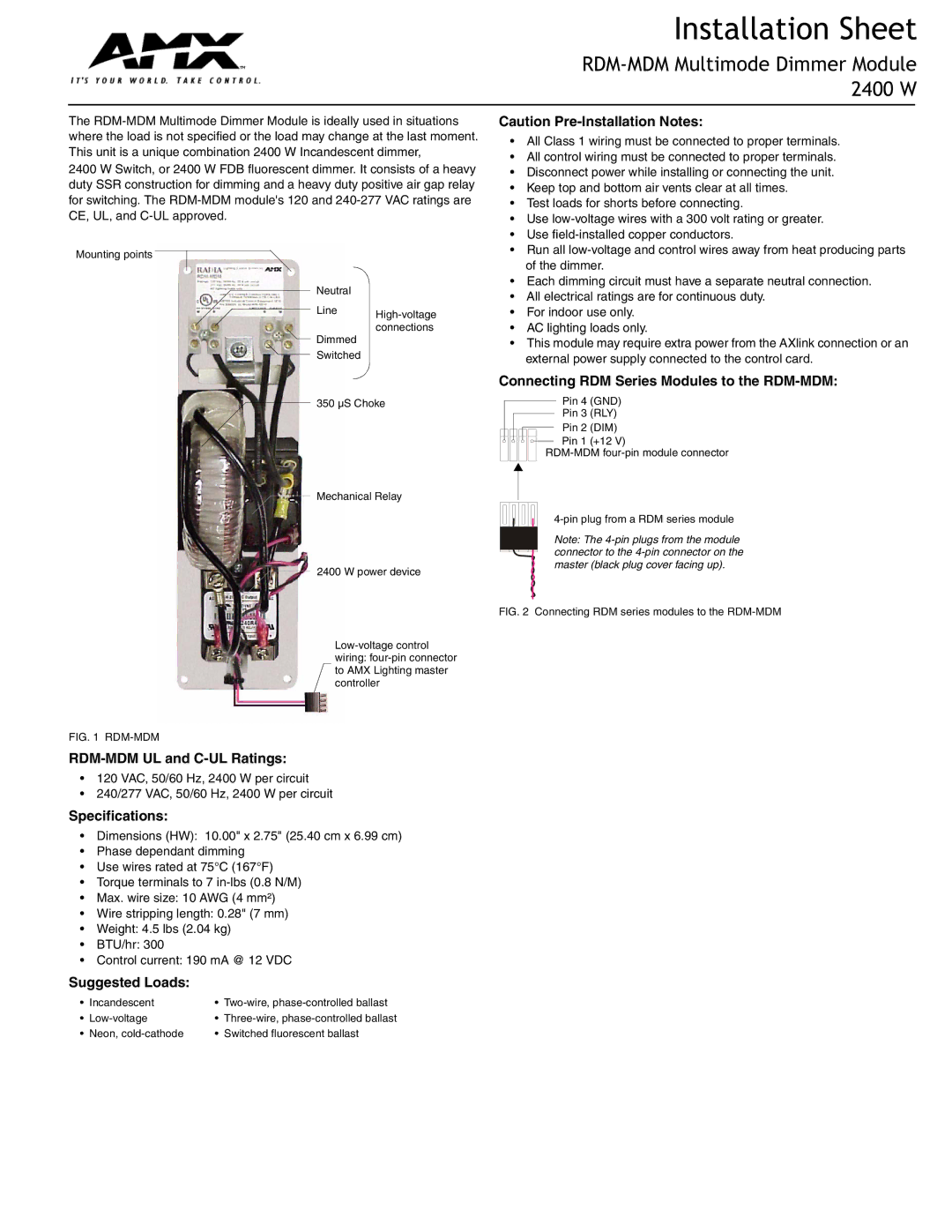
Mounting points
Neutral
Line
Dimmed
Switched
of the dimmer. |
• Each dimming circuit must have a separate neutral connection. |
• All electrical ratings are for continuous duty. |
• For indoor use only. |
• AC lighting loads only. |
• This module may require extra power from the AXlink connection or an |
external power supply connected to the control card. |
Connecting RDM Series Modules to the RDM-MDM:
350 µS Choke
Mechanical Relay
2400 W power device
Pin 4 (GND)
Pin 3 (RLY)
Pin 2 (DIM)
Pin 1 (+12 V)
Note: The
FIG. 2 Connecting RDM series modules to the RDM-MDM
FIG. 1 RDM-MDM
•120 VAC, 50/60 Hz, 2400 W per circuit
•240/277 VAC, 50/60 Hz, 2400 W per circuit
Specifications:
•Dimensions (HW): 10.00" x 2.75" (25.40 cm x 6.99 cm)
•Phase dependant dimming
•Use wires rated at 75°C (167°F)
•Torque terminals to 7
•Max. wire size: 10 AWG (4 mm²)
•Wire stripping length: 0.28" (7 mm)
•Weight: 4.5 lbs (2.04 kg)
•BTU/hr: 300
•Control current: 190 mA @ 12 VDC
Suggested Loads:
• | Incandescent | • | |
• | • | ||
• Neon, | • Switched fluorescent ballast | ||