User Manual
Hipulse - Single Phase ‘1+N’ UPS System | 130 kVA - 110V |
8.2Installation procedure
8.2.1Preliminary Checks
Be sure that a parallel kit is present and fitted in each of the modules, and that the modules are of the same rating and with the same software and hardware release (see section 4.1.2 – Info window)
WARNING
Fitting of the parallel kits and board setting required to convert from Single Module to 1+N must be made by qualified and trained personnel. This operation involves also setting of system with separate batteries or common batteries.
8.2.2Protective Devices
Refer to the instructions supplied in Chapter 3 – Electrical Installation - Section 3.1.6.
8.2.3Power Cables
Input Bypass and Rectifier, outputs of module as described in Chapter 3.
8.2.4Control Cables
Inter-module control
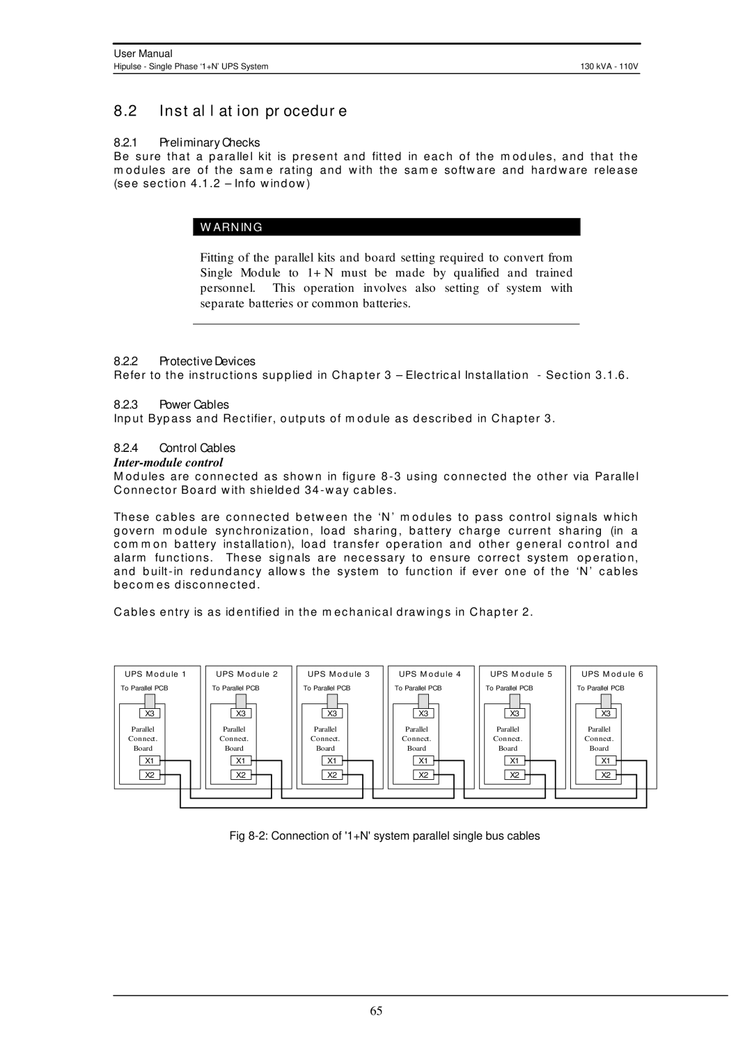
Modules are connected as shown in figure
These cables are connected between the ‘N’ modules to pass control signals which govern module synchronization, load sharing, battery charge current sharing (in a common battery installation), load transfer operation and other general control and alarm functions. These signals are necessary to ensure correct system operation, and
Cables entry is as identified in the mechanical drawings in Chapter 2.
UPS Module 1
To Parallel PCB
X3
Parallel
Connect.
Board
X1
X2
UPS Module 2
To Parallel PCB
X3
Parallel
Connect.
Board
X1
X2
UPS Module 3
To Parallel PCB
X3
Parallel
Connect.
Board
X1
X2
UPS Module 4
To Parallel PCB
X3
Parallel
Connect.
Board
X1
X2
UPS Module 5
To Parallel PCB
X3
Parallel
Connect.
Board
X1
X2
UPS Module 6
To Parallel PCB
X3
Parallel
Connect.
Board
X1
X2
Fig 8-2: Connection of '1+N' system parallel single bus cables
65