User Manual
Hipulse - Single Phase ‘1+N’ UPS System | 130 kVA - 110V |
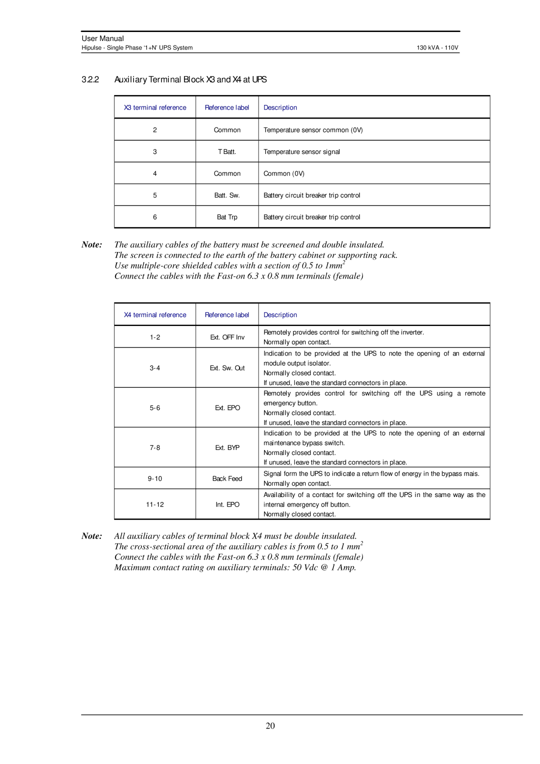
3.2.2Auxiliary Terminal Block X3 and X4 at UPS
X3 terminal reference | Reference label | Description |
|
|
|
2 | Common | Temperature sensor common (0V) |
|
|
|
3 | T Batt. | Temperature sensor signal |
|
|
|
4 | Common | Common (0V) |
|
|
|
5 | Batt. Sw. | Battery circuit breaker trip control |
|
|
|
6 | Bat Trp | Battery circuit breaker trip control |
|
|
|
Note: The auxiliary cables of the battery must be screened and double insulated. The screen is connected to the earth of the battery cabinet or supporting rack. Use
Connect the cables with the
X4 terminal reference | Reference label | Description | |
|
|
| |
Ext. OFF Inv | Remotely provides control for switching off the inverter. | ||
Normally open contact. | |||
|
| ||
|
| Indication to be provided at the UPS to note the opening of an external | |
Ext. Sw. Out | module output isolator. | ||
Normally closed contact. | |||
|
| ||
|
| If unused, leave the standard connectors in place. | |
|
| Remotely provides control for switching off the UPS using a remote | |
Ext. EPO | emergency button. | ||
Normally closed contact. | |||
|
| ||
|
| If unused, leave the standard connectors in place. | |
|
| Indication to be provided at the UPS to note the opening of an external | |
Ext. BYP | maintenance bypass switch. | ||
Normally closed contact. | |||
|
| ||
|
| If unused, leave the standard connectors in place. | |
Back Feed | Signal form the UPS to indicate a return flow of energy in the bypass mais. | ||
Normally open contact. | |||
|
| ||
|
| Availability of a contact for switching off the UPS in the same way as the | |
Int. EPO | internal emergency off button. | ||
|
| Normally closed contact. |
Note: All auxiliary cables of terminal block X4 must be double insulated.
The
Connect the cables with the
Maximum contact rating on auxiliary terminals: 50 Vdc @ 1 Amp.
20