User Manual
Hipulse - Single Phase ‘1+N’ UPS System | 130 kVA - 110V |
CHAPTER 4
Operator Control and Display Panel
4.1Introduction
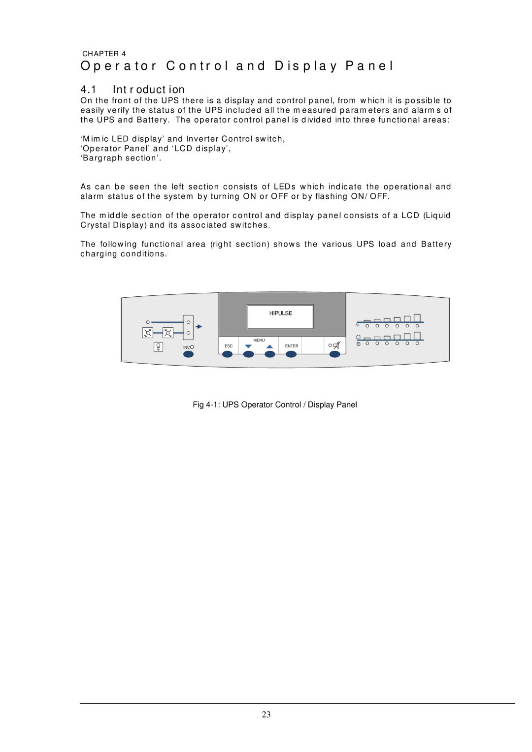
On the front of the UPS there is a display and control panel, from which it is possible to easily verify the status of the UPS included all the measured parameters and alarms of the UPS and Battery. The operator control panel is divided into three functional areas:
‘Mimic LED display’ and Inverter Control switch, ‘Operator Panel’ and ‘LCD display’, ‘Bargraph section’.
As can be seen the left section consists of LEDs which indicate the operational and alarm status of the system by turning ON or OFF or by flashing ON/ OFF.
The middle section of the operator control and display panel consists of a LCD (Liquid Crystal Display) and its associated switches.
The following functional area (right section) shows the various UPS load and Battery charging conditions.
|
| HIPULSE |
|
| % |
|
| MENU |
INV | ESC | ENTER |
|
|
Fig 4-1: UPS Operator Control / Display Panel
23