User Manual
Hipulse - Single Phase ‘1+N’ UPS System | 130 kVA - 110V |
Maintenance Bypass |
|
|
|
|
|
Isolator Q3 | Maintenance Bypass Line |
|
|
|
|
|
|
|
|
| |
Bypass Isolator Q2 | Static Bypass Line |
|
|
|
|
|
|
|
|
| |
|
|
| Output |
|
|
RECTIFIER | DC Bus | STATIC | Isolator Q4 |
| |
INVERTER | SWITCH |
|
|
| |
Input |
|
|
| UPS 1 | |
|
|
|
| ||
Isolator Q1 |
|
|
|
| |
|
|
|
| Output | |
| UPS MODULE 1 | 3 | 4 | ||
| Supply | ||||
|
|
| X4 |
| |
| Battery | Inter Module | Ext. |
|
|
BATTERY 1 | Sw . |
|
| ||
C.B. 1 | Control Bus | Out |
|
| |
Maintenance Bypass |
|
|
|
|
|
Isolator Q3 | Maintenance Bypass Line |
|
|
|
|
|
|
|
|
| |
Bypass Isolator Q2 | Static Bypass Line |
|
|
|
|
|
|
|
|
| |
|
|
|
| Output |
|
RECTIFIER | DC Bus | STATIC |
| Isolator Q4 |
|
INVERTER | SWITCH |
|
|
| |
Input |
|
|
| UPS 2 | |
|
|
|
| ||
Isolator Q1 |
|
|
|
| Output |
| UPS MODULE 2 | 3 | 4 | ||
| Supply | ||||
|
|
|
| X4 | |
|
|
|
|
| |
| Battery |
|
| Ext. |
|
BATTERY 2 | Inter Module |
| Sw . |
| |
C.B. 12 |
|
| |||
Control Bus |
| Out |
| ||
UPS MODULE 6
Ext.
Sw .
Out
I N P U T
D I S T R I B U T I O N
UPS 6
Output
Supply
D I S T R I B U T I O N O F L O A D
D I S T R I B U T I O N
P A N E L
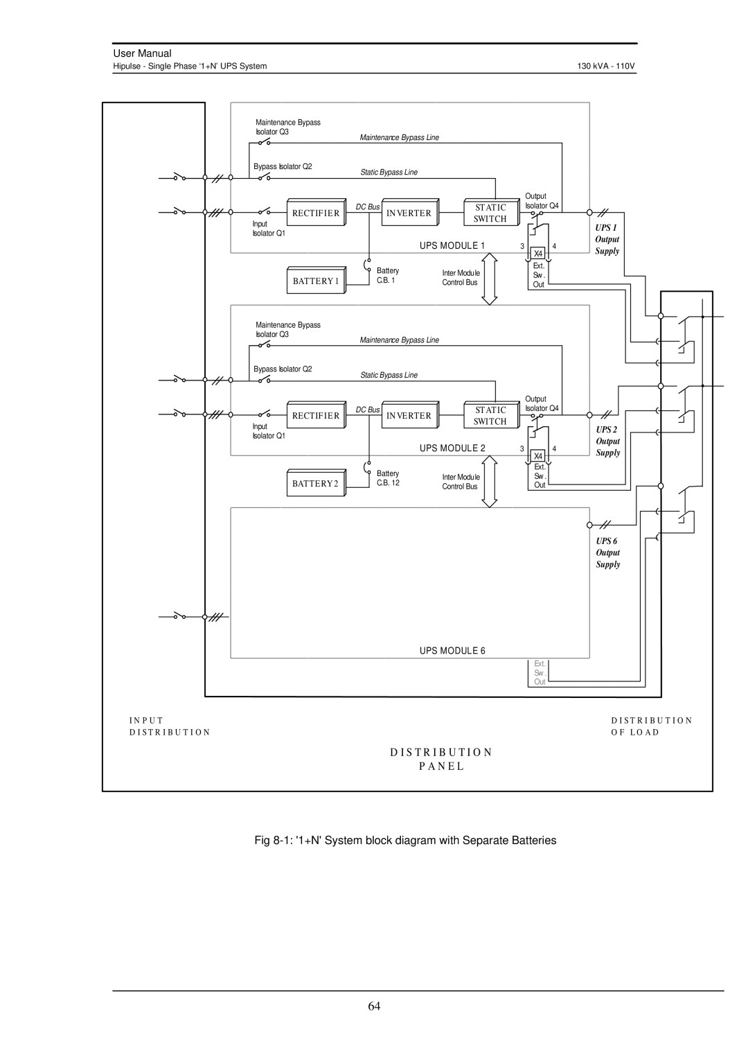
Fig 8-1: '1+N' System block diagram with Separate Batteries
64
