User Manual
Hipulse - Single Phase ‘1+N’ UPS System | 130 kVA - 110V |
During normal operation both the rectifier and inverter sections are active and provide regulated load power whilst simultaneously float charging the battery. In the event of a mains power failure, the rectifier becomes inoperative and the inverter is powered solely from the battery. Critical load power is maintained under these conditions until battery is fully discharged, where upon the UPS shuts down. The end of battery discharge is assumed when the battery voltage falls below a preset value (i.e. 330 / 340V d.c. for a 400 V a.c. system).
The period for which the load can be maintained following a mains power failure is known as the ‘System’s Autonomy Time’ and is dependent upon both the battery A/Hr capacity and the applied percentage load.
1.2.2 Bypass Supplies
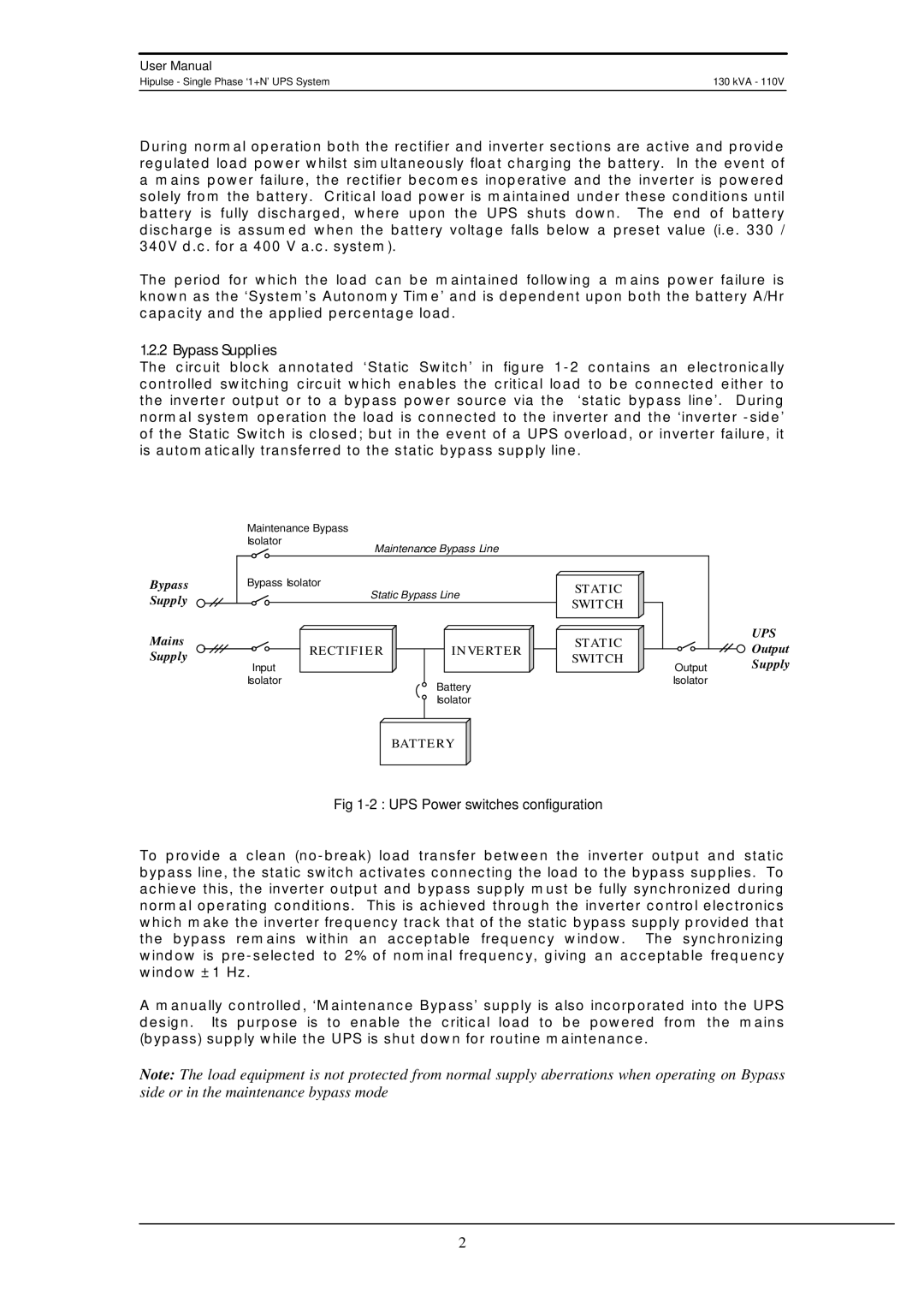
The circuit block annotated ‘Static Switch’ in figure
Bypass Supply
Mains Supply
Maintenance Bypass
Isolator
Maintenance Bypass Line
Bypass Isolator |
| STATIC | |
Static Bypass Line | |||
SWITCH | |||
|
| ||
RECTIFIER | INVERTER | STATIC | |
SWITCH | |||
Input |
| ||
| Output | ||
Isolator | Battery | Isolator | |
|
| ||
| Isolator |
| |
| BATTERY |
| |
UPS
Output
Supply
Fig 1-2 : UPS Power switches configuration
To provide a clean
A manually controlled, ‘Maintenance Bypass’ supply is also incorporated into the UPS design. Its purpose is to enable the critical load to be powered from the mains (bypass) supply while the UPS is shut down for routine maintenance.
Note: The load equipment is not protected from normal supply aberrations when operating on Bypass side or in the maintenance bypass mode
2