User Manual
Hipulse - Single Phase ‘1+N’ UPS System | 130 kVA - 110V |
3.2Control cables
3.2.1Battery Control
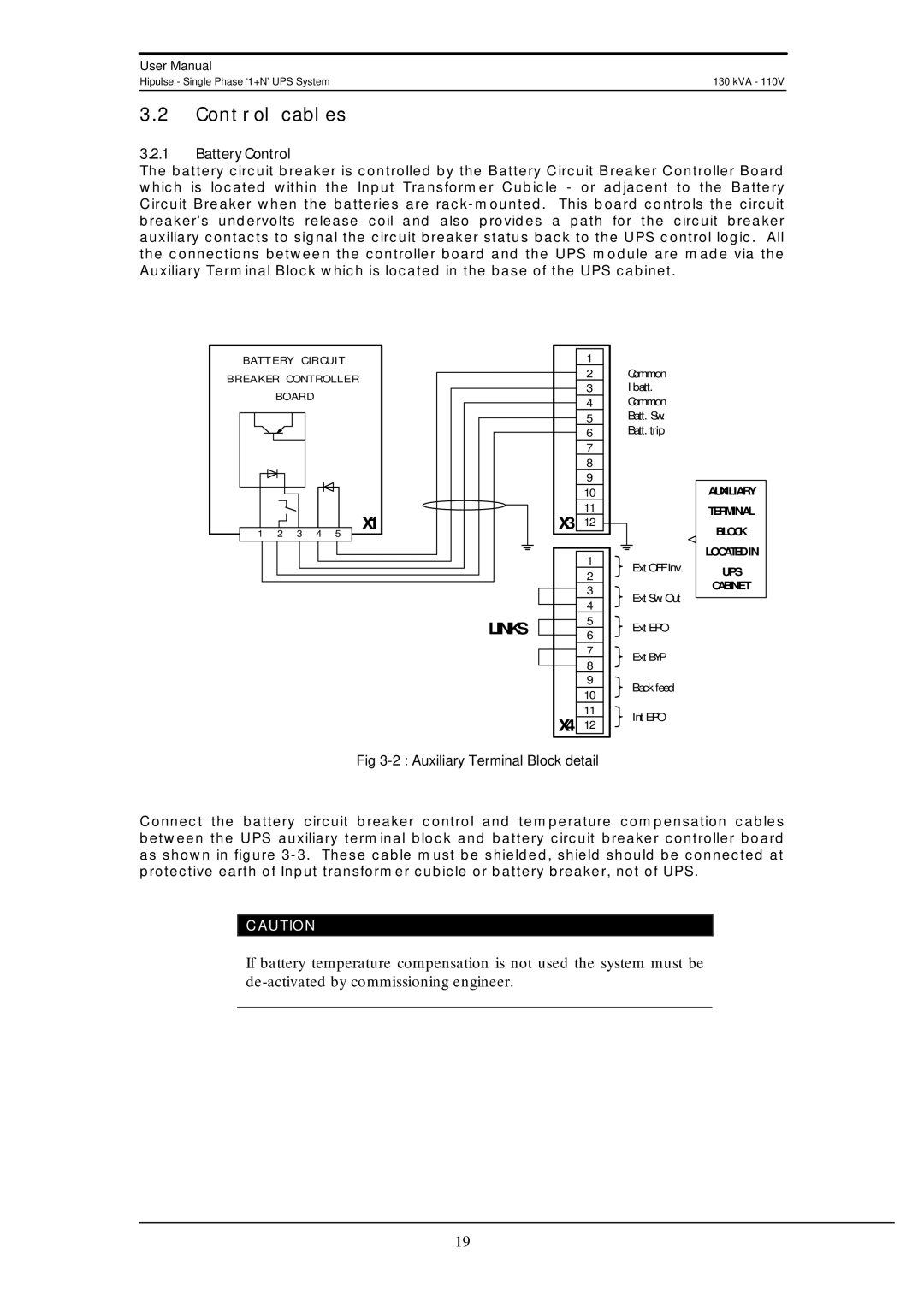
The battery circuit breaker is controlled by the Battery Circuit Breaker Controller Board which is located within the Input Transformer Cubicle - or adjacent to the Battery Circuit Breaker when the batteries are
B AT T E RY CI RCU IT | ||||
B R EAK ER CON TROL L E R | ||||
| BOARD |
|
| |
1 | 2 | 3 | 4 | X1 |
5 | ||||
LINKS
1
2
3
4
5
6
7
8
9
10
11
X3 12
1
2
3
4
5
6
7
8
9
10
11
X4 12
Common
I batt.
Common
Batt. Sw.
Batt. trip
| AUXILIARY |
| TERMINAL |
| BLOCK |
| LOCATED IN |
Ext OFF Inv. | UPS |
| |
Ext Sw. Out | CABINET |
| |
| |
Ext EPO |
|
Ext BYP |
|
Back feed |
|
Int EPO |
|
Fig 3-2 : Auxiliary Terminal Block detail
Connect the battery circuit breaker control and temperature compensation cables between the UPS auxiliary terminal block and battery circuit breaker controller board as shown in figure
CAUTION
If battery temperature compensation is not used the system must be
19