MICROSTEP SELECTION
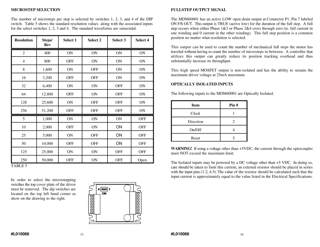
The number of microsteps per step is selected by switches 1, 2, 3, and 4 of the DIP switch. Table 5 shows the standard resolution values along with the associated inputs for the select switches 1, 2, 3 and 4. The standard waveforms are sinusoidal.
Resolution | Steps/ | Select 1 | Select 2 | Select 3 | Select 4 | |
| Rev |
|
|
|
|
|
|
|
|
|
|
|
|
|
|
|
|
|
|
|
2 | 400 | ON | ON | ON | ON |
|
|
|
|
|
|
|
|
4 | 800 | OFF | ON | ON | ON |
|
|
|
|
|
|
|
|
8 | 1,600 | ON | OFF | ON | ON |
|
|
|
|
|
|
|
|
16 | 3,200 | OFF | OFF | ON | ON |
|
|
|
|
|
|
|
|
32 | 6,400 | ON | ON | OFF | ON |
|
|
|
|
|
|
|
|
64 | 12,800 | OFF | ON | OFF | ON |
|
|
|
|
|
|
|
|
128 | 25,600 | ON | OFF | OFF | ON |
|
|
|
|
|
|
|
|
256 | 51,200 | OFF | OFF | OFF | ON |
|
|
|
|
|
|
|
|
|
|
|
|
|
| |
5 | 1,000 | ON | ON | ON | OFF |
|
|
|
|
|
|
|
|
10 | 2,000 | OFF | ON | ON | OFF |
|
|
|
|
|
|
|
|
25 | 5,000 | ON | OFF | ON | OFF |
|
|
|
|
|
|
|
|
50 | 10,000 | OFF | OFF | ON | OFF |
|
|
|
|
|
|
|
|
125 | 25,000 | ON | ON | OFF | OFF |
|
|
|
|
|
|
|
|
250 | 50,000 | OFF | ON | OFF | Open |
|
TABLE 5
In order to select the microstepping swicthes the top cover plate of the driver must be removed. The dip switches are located on the top left hand corner as show on the drawing to the right.
FULLSTEP OUTPUT SIGNAL
The MDM40001 has an active LOW open drain output at Connector P1, Pin 7 labeled ON F/S OUT. This output is TRUE (active low) for the duration of the full step. A full step occurs when either Phase 1&3 or Phase 2&4 cross through zero (ie. full current in one winding and 0 current in the other winding). This full step position is a common position no matter what resolution is selected.
This output can be used to count the number of mechanical full steps the motor has traveled without having to count the number of microsteps in between. A controller that utilizes this output can greatly reduce its position tracking overhead and thus substantially increase its throughput.
This high speed MOSFET output is
OPTICALLY ISOLATED INPUTS
The following inputs to the MDM40001 are Optically Isolated.
Item | Pin # |
|
|
Clock | 1 |
|
|
Direction | 2 |
|
|
On/Off | 4 |
|
|
Reset | 5 |
|
|
WARNING! If using a voltage other than +5VDC, the current through the optocoupler must NOT exceed the maximum limit.
The Isolated inputs may be powered by a DC voltage other than +5 VDC. In doing so, care should be taken to limit this current, an external resistor should be placed in series with the input pins
#L010068 | 15 | #L010068 | 16 |