Evaluation Board User Guide
UG-002
One Technology Way • P.O. Box 9106 • Norwood, MA
Evaluating the AD9551 Multiservice Clock Generator
FEATURES
Simple power connection using USB connection and
LDOs are easily bypassed for power measurements
2 reference inputs
2 PLL lock detect outputs
Microsoft
Easy access to digital I/O and diagnostic signals via I/O header
Status LEDs for diagnostic signals USB computer interface
Dip switch configurable for manual operation
Software calculator provides flexibility, allowing programming almost any rational input/output frequency ratio
GENERAL DESCRIPTION
This user guide describes the hardware and software of the AD9551 evaluation board and includes detailed schematics and PCB layout artwork. The AD9551 Revision D evaluation board is a compact, easy to use platform for evaluating all features of the AD9551 multiservice clock generator.
The AD9551 accepts one or two reference input signals to synthesize one or two output signals. The AD9551 uses a
The AD9551 uses an external crystal and an internal DCXO to provide for holdover operation. If both references fail, the device maintains a steady output signal. This may mislead you to believe that the PLL is locked and the board is configured properly. A simple test is to move the input REF A or REF B clock a few kilo- hertz and verify that the changes in output frequency track the input.
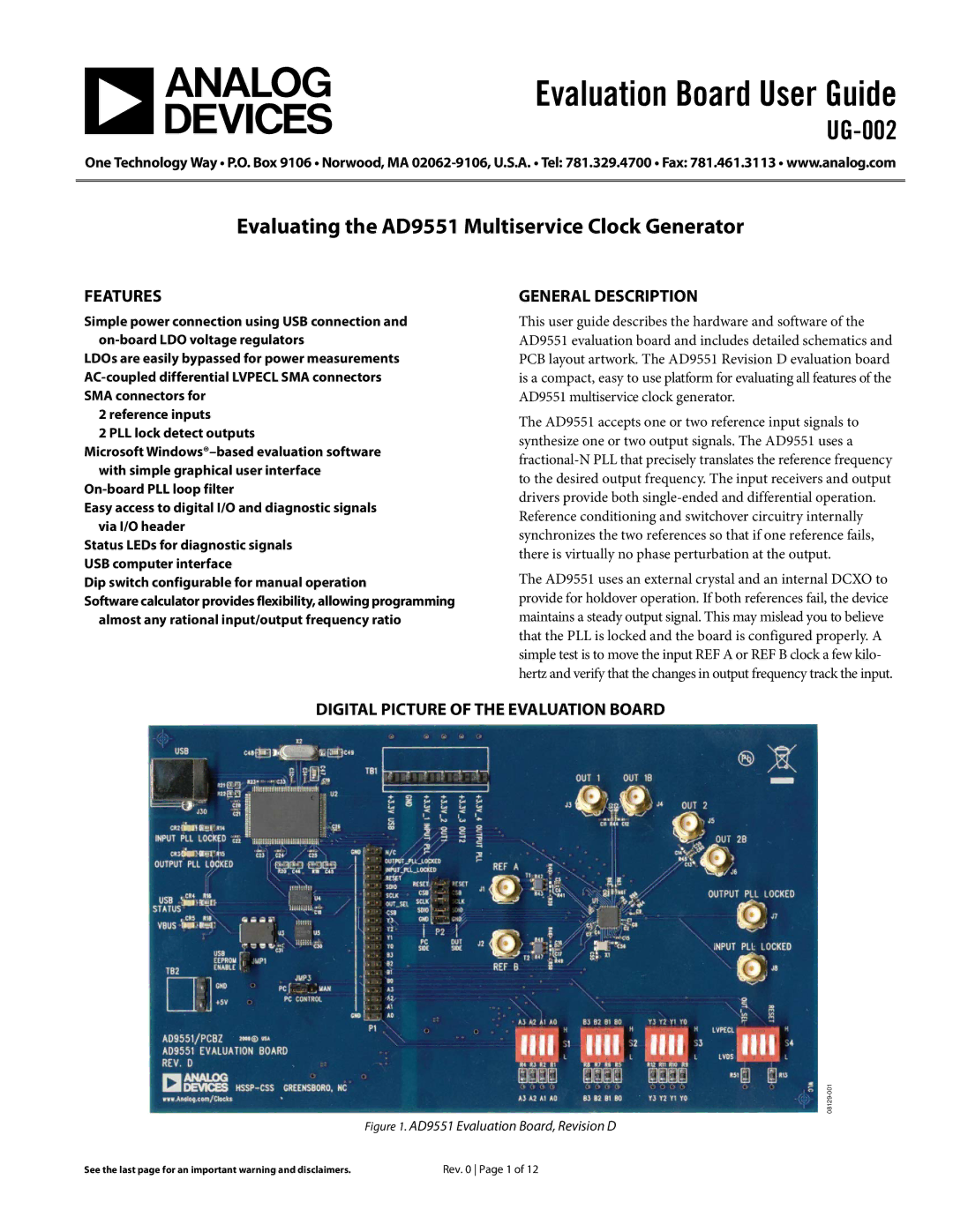
DIGITAL PICTURE OF THE EVALUATION BOARD
Figure 1. AD9551 Evaluation Board, Revision D
See the last page for an important warning and disclaimers. | Rev. 0 Page 1 of 12 |