GROUND POLE INSTALLATION (96cm System)
AZ-EL MOUNT WITH M8 INSERT AND SET SCREW
2.88" or
3.00" O.D.
C | ANT |
|
| 1" to 2" | 41.5" |
36.4" | SLOPE FOR |
|
|
| |
WATER RUN OFF |
| |
72" | GRADE |
|
|
| |
| 40" |
|
#3 REBAR x |
|
|
DIA. OF PIER |
| d |
|
|
|
| ||
INSERT THRU HOLE |
|
|
| BELOW |
| |||
|
|
|
| MIN. |
|
|
| |
IN TUBE & CENTER |
|
|
| FROST LINE | ||||
|
|
| ||||||
|
|
|
|
|
|
| ||
DIA.
STANDARD
PIER FOUNDATION
|
|
| 2.88" or |
|
|
|
| 3.00" O.D. | |
| 36.4" |
| 1" to 2" |
|
|
| SLOPE FOR | ||
NOTE: |
|
| WATER RUN OFF | |
|
|
|
| |
50" depth may be | 72" |
| GRADE | |
|
|
| ||
increased, |
|
|
|
|
concrete and |
|
|
|
|
length of rebar |
|
|
| 50" |
will increase |
|
| (SEE | |
accordingly. |
|
| NOTE) |
|
|
|
| 2" |
|
#3 REBAR x DIA. OF PIER, INSERT |
| APPROX. | ||
THRU HOLE IN TUBE & CENTER |
|
|
| |
| (4)#3x24"MIN. | d |
|
|
| AT 90o APART | 2" |
| |
| MIN. |
| ||
| (SEE NOTE) |
|
| |
| DIA. |
|
| |
|
|
|
| |
|
|
| BELOW | |
|
|
| FROST LINE | |
DEEP FROST
LINE FOUNDATION
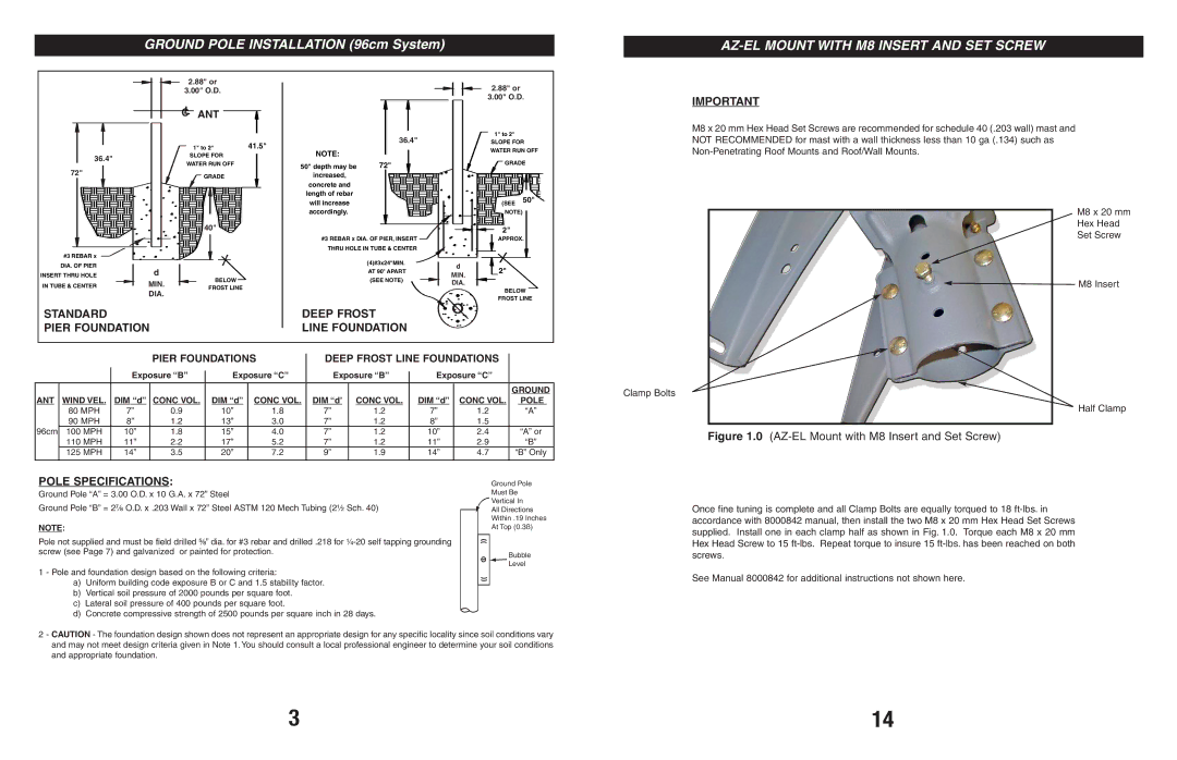
IMPORTANT
M8 x 20 mm Hex Head Set Screws are recommended for schedule 40 (.203 wall) mast and NOT RECOMMENDED for mast with a wall thickness less than 10 ga (.134) such as
M8 x 20 mm
Hex Head
Set Screw
![]() M8 Insert
M8 Insert
|
|
|
| PIER FOUNDATIONS |
| DEEP FROST LINE FOUNDATIONS |
| |||||||
|
|
| Exposure “B” |
| Exposure “C” | Exposure “B” |
| Exposure “C” |
| |||||
|
|
|
|
|
| |||||||||
|
|
|
|
|
|
|
|
|
|
|
|
|
|
|
|
|
|
|
|
|
|
|
|
|
|
|
|
| GROUND |
ANT | WIND VEL. | DIM “d” | CONC VOL. |
| DIM “d” | CONC VOL. | DIM “d’ | CONC VOL. |
| DIM “d” | CONC VOL. | POLE | ||
| 80 MPH | 7” | 0.9 |
| 10” | 1.8 |
| 7” | 1.2 |
| 7” | 1.2 | “A” | |
| 90 MPH | 8” | 1.2 |
| 13” | 3.0 |
| 7” | 1.2 |
| 8” | 1.5 |
| |
96cm | 100 MPH | 10” | 1.8 |
| 15” | 4.0 |
| 7” | 1.2 |
| 10” | 2.4 | “A” or | |
| 110 MPH | 11” | 2.2 |
| 17” | 5.2 |
| 7” | 1.2 |
| 11” | 2.9 | “B” | |
| 125 MPH | 14” | 3.5 |
| 20” | 7.2 |
| 9” | 1.9 |
| 14” | 4.7 | “B” Only | |
|
|
|
|
|
|
|
|
|
|
|
|
|
|
|
Clamp Bolts
Half Clamp
Figure 1.0 (AZ-EL Mount with M8 Insert and Set Screw)
POLE SPECIFICATIONS:
Ground Pole “A” = 3.00 O.D. x 10 G.A. x 72” Steel
Ground Pole “B” = 2⁷⁄₈ O.D. x .203 Wall x 72” Steel ASTM 120 Mech Tubing (2¹⁄₂ Sch. 40)
NOTE:
Pole not supplied and must be field drilled ⁵⁄₈” dia. for #3 rebar and drilled .218 for
1 - Pole and foundation design based on the following criteria:
a)Uniform building code exposure B or C and 1.5 stability factor.
b)Vertical soil pressure of 2000 pounds per square foot.
c)Lateral soil pressure of 400 pounds per square foot.
d)Concrete compressive strength of 2500 pounds per square inch in 28 days.
Ground Pole
Must Be
Vertical In
All Directions
Within .19 Inches
At Top (0.3ß)
Bubble
Level
Once fine tuning is complete and all Clamp Bolts are equally torqued to 18
See Manual 8000842 for additional instructions not shown here.
2 - CAUTION - The foundation design shown does not represent an appropriate design for any specific locality since soil conditions vary and may not meet design criteria given in Note 1. You should consult a local professional engineer to determine your soil conditions and appropriate foundation.
3 | 14 |