ASSEMBLY AND INSTALLATION
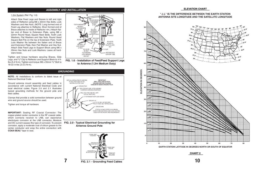
ELEVATION CHART
1.2m System (Ref. Fig. 1.6)
Attach Side Feed Legs and Braces to left and right sides of Reflector using M6 x 20mm Hex Bolts, Lock Washers and Hex Nuts. (NOTE: Long formed end of Feed Leg attaches to Reflector. Short formed end of Brace attaches to inside of Reflector rim.) Attach flat- ten end of Brace to Extension Plate, using M6 x 22mm Round Head, Square Neck Bolts, Tooth Lock Washers, Flat Washers and Hex Nuts. Round Head Square Bolt Fits on the top of Extension Plate. Tooth Lock Washer fits between the flatten end of Brace and Extension Plate, then Flat Washer and Hex Nut. Attach Side Feed Legs to Support Block using M6 x 20mm Hex Nuts and Lock Washers. Leave all hard- ware loose.
Tighten and torque hardware securing Braces, Side Legs, and “U” Clip to Reflector and Support Block to 4 ft- lbs (5.4
| RD HD SQ NK BOLT |
|
| TOOTH WASHER |
|
| FLAT WASHER |
|
TOOTH WASHER | HEX NUT |
|
(2 REQ) |
| |
HEX BOLT |
|
|
FLAT WASHER | M6 x 20mm |
|
(2 REQ) |
| |
HEX BOLTS |
| |
|
| |
| LOCK WASHERS |
|
| HEX NUTS |
|
(2 | BRACE | |
|
| |
BLOCK | SIDE FEED |
|
LEGS |
| |
| RD HD SQ | |
| (2 REQ) | |
HEX BOLT |
| NK BOLT & |
| ELASTIC LOCK | |
LOCK WAHER |
| |
| NUT | |
(2 REQ) |
| |
|
| |
RD HD SQ |
| "U" CLIP |
NK BOLT |
| BOTTOM FEED |
FLAT WASHER | ||
LOCK WASHER | SUPPORT TUBE | |
HEX NUT |
|
|
FIG. 1.6 - Installation of Feed/Feed Support Legs to Antenna (1.2m Medium Duty)
"L" IS THE DIFFERENCE BETWEEN THE EARTH STATION ANTENNA SITE LONGITUDE AND THE SATELLITE LONGITUDE
|
|
|
|
|
|
|
|
|
| 125O |
|
|
|
|
|
|
|
|
|
|
|
|
|
| O |
|
| |
90 |
|
|
|
|
| 50O |
| 120O 1 |
|
|
|
|
|
|
|
|
|
|
|
| O | 65 | O |
| ||||
|
|
|
|
|
|
|
| O |
| O |
|
|
|
|
|
|
| O | O | 70 |
| 50 |
| |||||
|
|
|
|
|
|
|
|
|
|
|
| 15 |
| 110 |
| O |
| O |
| O | O | 80 | 75 |
|
| O |
| |
|
|
|
| 47. | 5 | O |
|
|
|
|
|
|
| 105 |
| 100 |
| 95O | 90 | 85 |
|
|
|
| .5 |
| ||
|
|
|
|
|
|
|
|
|
|
|
|
|
|
|
|
|
|
|
|
|
|
|
|
|
| 47 |
| |
|
|
|
| 45 | O |
|
|
|
|
|
|
|
|
|
|
|
|
|
|
|
|
|
|
| O |
| ||
|
|
|
|
|
|
|
|
|
|
|
|
|
|
|
|
|
|
|
|
|
|
| 45 |
| ||||
|
|
|
|
|
|
|
|
|
|
|
|
|
|
|
|
|
|
|
|
|
|
|
|
| ||||
|
|
|
|
|
|
|
|
|
|
|
|
|
|
|
|
|
|
|
|
|
|
|
|
|
|
|
| |
|
| 42. |
|
|
|
|
|
|
|
|
|
|
|
|
|
|
|
|
|
|
|
|
|
|
| O | ||
|
|
| O |
|
|
|
|
|
|
|
|
|
|
|
|
|
|
|
|
|
|
|
|
| .5 | |||
|
| 5 |
|
|
|
|
|
|
|
|
|
|
|
|
|
|
|
|
|
|
|
| 2 | |||||
|
|
|
|
|
|
|
|
|
|
|
|
|
|
|
|
|
|
|
|
|
|
|
|
|
| 4 |
| |
80 | 5O |
| 40O |
|
|
|
|
|
|
|
|
|
|
|
|
|
|
|
|
|
|
|
|
| O |
| ||
3 | 7. |
|
|
|
|
|
|
|
|
|
|
|
|
|
|
|
|
|
|
|
|
|
|
|
| 40 |
| |
| 5 | O |
|
|
|
|
|
|
|
|
|
|
|
|
|
|
|
|
|
|
|
|
|
|
| |||
|
|
|
|
|
|
|
|
|
|
|
|
|
|
|
|
|
|
|
|
|
|
|
| O |
| |||
|
|
|
|
|
|
|
|
|
|
|
|
|
|
|
|
|
|
|
|
|
|
|
|
|
|
| .5 |
|
| 10O |
|
|
|
|
|
|
|
|
|
|
|
|
|
|
|
|
|
|
|
|
|
|
|
|
| 37 |
|
|
|
|
| 35O |
|
|
|
|
|
|
|
|
|
|
|
|
|
|
|
|
|
| O |
|
| |||
|
|
|
|
|
|
|
|
|
|
|
|
|
|
|
|
|
|
|
|
|
|
|
|
|
|
|
| |
|
|
|
| 32.5O |
|
|
|
|
|
|
|
|
|
|
|
|
|
|
|
|
| 35 |
|
| ||||
|
|
|
|
|
|
|
|
|
|
|
|
|
|
|
|
|
|
|
|
|
| O |
| |||||
|
|
|
|
|
|
|
|
|
|
|
|
|
|
|
|
|
|
|
|
|
|
|
|
|
|
| .5 |
|
70 | O |
|
|
|
|
|
|
|
|
|
|
|
|
|
|
|
|
|
|
|
|
|
|
|
| 32 |
| |
| 15 |
|
|
|
|
|
| 30 | O |
|
|
|
|
|
|
|
|
|
|
|
|
|
|
|
|
| ||
|
|
|
|
|
|
|
|
|
|
|
|
|
|
|
|
|
|
|
|
|
| O |
|
|
| |||
|
|
|
|
|
|
|
|
|
|
|
|
|
|
|
|
|
|
|
|
|
|
|
|
|
|
|
| |
|
|
|
|
|
|
| 27.5 | O |
|
|
|
|
|
|
|
|
|
|
|
|
|
| 30 |
|
|
| ||
| 20O |
|
|
|
|
|
|
|
|
|
|
|
|
|
|
|
|
|
|
|
|
| O |
|
| |||
|
|
|
|
|
| 25 | O |
|
|
|
|
|
|
|
|
|
|
|
|
|
|
| 27.5 |
|
| |||
|
|
|
|
|
|
|
|
|
|
|
|
|
|
|
|
|
|
|
|
|
|
|
|
|
| |||
|
|
|
|
|
|
|
|
|
|
|
|
|
|
|
|
|
|
|
|
|
|
|
| O |
|
| ||
|
|
|
|
|
|
|
|
|
|
|
|
|
|
|
|
|
|
|
|
|
|
|
|
|
|
|
| |
|
|
|
|
|
|
|
|
|
|
|
|
|
|
|
|
|
|
|
|
|
|
|
|
| 25 |
|
| |
60 | 25O |
|
|
|
|
|
|
|
|
|
|
|
|
|
|
|
|
|
|
|
|
|
|
|
|
|
|
|
|
|
|
|
|
|
|
|
|
|
|
|
|
|
|
|
|
|
|
|
|
|
|
|
|
|
|
| |
GROUNDING
DEGREES | 50 |
|
| 30O |
| ||
|
|
| |||||
|
|
|
|
|
| ||
|
|
|
|
|
| ||
|
|
|
|
|
| ||
|
|
|
|
|
|
| |
NOTE: All installations to conform to latest issue of National Electrical Code.
Ground antenna mount assembly and feed cables in accordance with current National Electrical Code and local electrical codes. Figure 2.0 and 2.1 illustrates typical grounding methods for the ground pole and feed cables.
Clamps that provide a solid connection between ground wire and ground source should be used.
Tighten and torque all hardware.
IMPORTANT: Sealing RF Coaxial Connector: The
NOTE: ALL INSTALLATION TO CONFORM | IMPORTANT | ||
TO THE LATEST ISSUE OF THE | DRILL HOLE AND ATTACH | ||
NATIONAL ELECTRIC CODE. | GROUND BEFORE POURING | ||
|
| GROUND POLE | CONCRETE INSIDE GROUND POLE. |
|
|
| |
|
|
| |
APPLY SEALANT HERE, AFTER ASSEMBLY,
TO IMPROVE CORROSION RESISTANCE
DRILL HOLE THRU ONE WALL WITH
7/32" DIA. TWIST DRILL
1/4" EXTENSION TOOTH LOCK WASHER
GROUND LUG | ||
APPROX. | ||
| ||
| TYPE "D" POINT, SELF TAPPING SCREW |
GROUND WIRE
(TYPICAL #10 AWG COPPER, #8 ALUMINUM)
REFER TO NEC SECTION 810 AND LOCAL ELECTRIC CODES FOR THE SPECIFIC AREA REQUIREMENTS.
FIG. 2.0 - Typical Electrical Grounding for
Antenna Ground Pole
| *COAXIAL CABLE |
| TO RECEIVER |
| *GROUND BLOCK |
| NEC SECTION |
| *COAXIAL CABLE |
| FROM LNB |
| *GROUNDWIRE |
| NEC SECTION |
| *ITEMS NOT |
| INCLUDED |
7 | FIG. 2.1 - Grounding Feed Cables |
IN |
| 35O |
|
|
|
|
|
|
|
|
|
|
|
|
|
|
|
| |
ELEVATION |
| 40O |
|
|
|
|
|
|
|
40 |
|
|
|
|
|
|
|
| |
| 45O |
|
|
|
|
|
|
| |
|
|
|
|
|
|
|
|
| |
| 30 | 50O |
|
|
|
|
|
|
|
|
|
|
|
|
|
|
|
| |
|
| 55O |
|
|
|
|
|
|
|
| 20 | 60O |
|
|
|
|
|
|
|
|
| 65O |
|
|
|
|
|
|
|
| 10 | 70O |
|
|
|
|
|
|
|
|
| 75O |
|
|
|
|
|
|
|
| 0 |
|
|
|
|
|
|
|
|
| 0 | 10 | 20 | 30 | 40 | 50 | 60 | 70 | 80 |
EARTH STATION LATITUDE IN DEGREES NORTH OR SOUTH OF EQUATOR
CHART 2
10