Installing the Motherboard
This manual does not cover CPU, RAM, or expansion card installation. Please consult your motherboard manual for specific mounting instructions and troubleshooting.
1.Lay the case down, with the open side facing up. The drive cages and power supply should be visible.
2.Make sure you have the correct I/O panel for your motherboard. If the panel provided with the case isn't suitable, please contact your mother- board manufacturer for the correct I/O panel.
3.Line up your motherboard with the standoff holes, and remember which holes are lined up. Not all motherboards will match with all of the provided holes; this is normal, and won't affect functionality. (In other words, there will likely be extra holes.)
4.Remove your motherboard by lifting it up.
5.Screw the brass standoffs into the threaded holes that line up with your motherboard. Do not overtighten the standoffs. Some standoffs may be
6.Place your motherboard on the brass standoffs.
7.Screw in your motherboard to the standoffs with the provided
Connecting the Power and LED
The power supply conforms to the latest ATX12V Version 2.0 standard. It is also
The power supply is also equipped with a
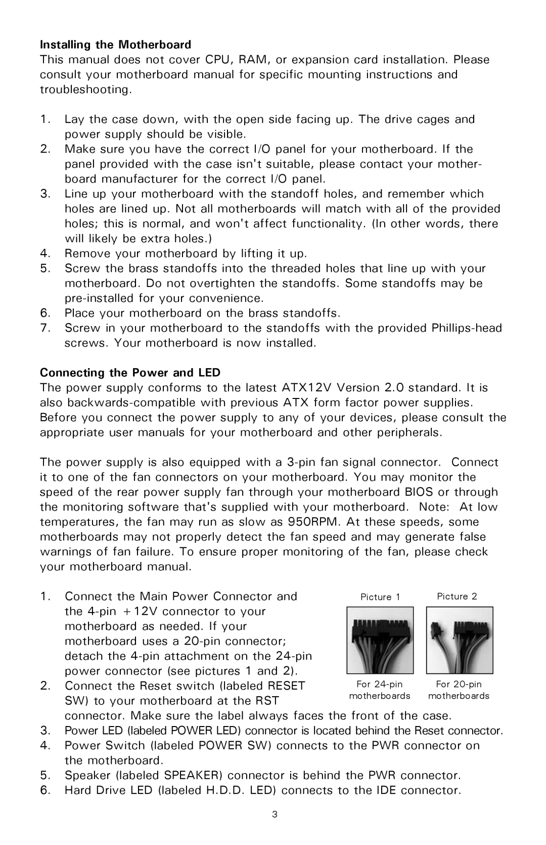
1. | Connect the Main Power Connector and | Picture 1 |
| Picture 2 |
| the |
|
|
|
|
|
|
| |
| motherboard as needed. If your |
|
|
|
| motherboard uses a |
|
|
|
| detach the |
|
|
|
| power connector (see pictures 1 and 2). |
|
|
|
|
|
|
| |
2. | Connect the Reset switch (labeled RESET | For |
| For |
| SW) to your motherboard at the RST | motherboards |
| motherboards |
|
|
|
|
connector. Make sure the label always faces the front of the case.
3.Power LED (labeled POWER LED) connector is located behind the Reset connector.
4.Power Switch (labeled POWER SW) connects to the PWR connector on the motherboard.
5.Speaker (labeled SPEAKER) connector is behind the PWR connector.
6.Hard Drive LED (labeled H.D.D. LED) connects to the IDE connector.
3