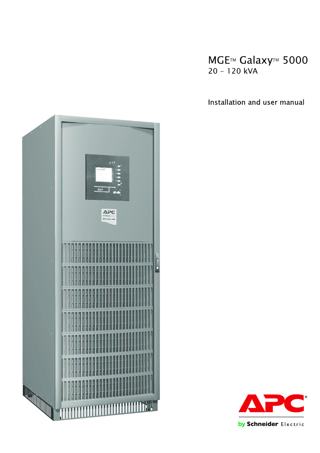
Manuals
/
Brands
/
Computer Equipment
/
Power Supply
/
APC
/
Computer Equipment
/
Power Supply
APC
5000 user manual
1
1
68
68
Download
68 pages, 3.16 Mb
MGE
TM
Galaxy
TM
5000
20 - 120 kVA
Installation and user manual
Contents
Main
Introduction
Safety
Safety rules
Special precautions
Safety of persons
Product safety
Foreword
Pictograms
Document Display
E S C D E L VOLT
17 mai
1. Presentation
2. Installation
3. Operation
4. Maintenance
5. Environment 6. Available options
7. Appendices
1.1 MGE
UPS cabinet
External battery cabinet / auxiliary cabinet
1.2 Inside the UPS cabinet, access to connections
Example of version with built-in battery
Simplified diagram of power connections
Power-connection terminal blocks (version with built-in battery)
1.3 Cabinet layout (normal or false floor)
Power-connection terminal blocks (version with external battery)
INTN card for auxiliary interconnections of parallel UPS units
+-
19 20 21
1.4 User-machine interface
1.5 Relay communication card
2.1 Location
2.2 Layout of cabinets
2.3 Removing the cardboard protecting the batteries
In the UPS
In the external battery cabinet
2.4 Required protective devices and cable sizes
Recommended upstream protection
Recommended downstream protection
Earth-leakage current
Required cable sizes
Required cable sizes for parallel UPS installations with an external bypass
2.5 2.5 System earthing arrangements
Without differential circuit breaker:
TNS upstream and TNS downstream installa tion
For separate Normal AC and Bypass AC lines from a single source.
With differential circuit breaker:
TNC upstream, TNS downstream
For separate Normal AC and Bypass AC lines from a single source
Installation with upstream IT and downstream TNS
For separate Normal AC and Bypass AC lines from a single source
Installation with upstream TT and downstream TT (with upstream differential protection)
Frequency converter (without Bypass AC input)
Upstream and downstream: TT, TN or IT system with neutral distributed
AB
Upstream and downstream: Neutral not distributed
Page
Q4S
Q3BP
Q5N
2.6 Connection of power cables in a single UPS unit
Interconnecting the cabinet earths UPS units with common normal and Bypass AC inputs
Frequency converter
UPS units with separate normal and Bypass AC inputs
2.7 Earth-cable connection for a single unit in a TNC earthing system
2.8 Connection of power cables for parallel UPS units
Equipotential bonding between parallel-connected units
Connection of earth cable and tying of cables
Redundant parallel configuration (maximum two UPS units for Pn)
UPS units with common normal and Bypass AC inputs
UPS units with separate normal and Bypass AC inputs
Frequency converter
14
17
17 18
16 15 18
AB AB
2.9 Connection of the 150 kVA external bypass cabinet
2.10 Connection of the 360 kVA external bypass cabinet
2.11 Connection of the 600 kVA external bypass cabinet
2.12 Auxiliary interconnections between UPS units in parallel configurat ions
Redundant parallel configuration (maximum two UPS units)
10 10 12 12 10 10 12 12
Parallel configuration for increased capacity (maximum four UPS units)
11 11
Q3BP
Q4S
11
2.13 Connection of general shutdown or emergency power off (EPO) terminal block
7
XMB 08 XMB 07 XMS 06
2.14 Connection of the relay communications card
Characteristics of the contacts on the relay communications card.
Communications card connection example
Adding communication cards
6 5 4 3 2 1 BA
carte de communication
source
2.15 Running the control/communications cables
Parallel UPS
2.16 Power connections for an external battery cabinet
2.17 Assembly and connection of an empty battery cabinet
Mounting the battery circuit breaker kit
Mounting the shelves and the battery cells
2.18 Control connections for an external battery cabinet
+
5
6
XR1
A B C
3.1 Shutting down a single UPS
3.2 Restarting a single UPS
~
3.3 Shutting down a parallel configuration
3.4 Restarting a parallel configuration
8
Q1 Q4S Q3BP Q5N QF1 13
9 11
IO 3s
39 40 42 41 43
3.6 Operating modes
Normal (double conversion) mode
ECO mode (single UPS only)
3.7 Load on battery power
Transfer to battery power
Operating mode
Frequency
Automatic bypass Battery
3.9 Relay contacts (communications card)
3.10 Display functions
?
4.1 Identification of alarms
4.2 Life Cycle Monitoring (LCM)
?
IO 3s
32
4.3 UPS isolation
Frequency converter
If supplied by the network via the Bypass AC channel:
UPS operating in ECO mode
If the load is supplied by the UPS with Bypass AC source present:
Parallel UPS configuration without external bypass cabinet
Shutdown and isolation of the second UPS unit:
Shutdown and isolation of the first UPS unit:
Parallel UPS configuration with external bypass cabinet
Shutdown and isolation of one UPS unit
Shutdown and isolation of all the UPS units:
4.4 Return to the normal position
Single UPS
Frequency converter
Parallel UPS configuration without external bypass cabinet
Restart the UPS unit for which switch Q3BP (10) is ON and the other switches are OFF.
Restart the UPS unit for which all switches are set to OFF.
Parallel UPS configuration with external bypass cabinet
4.5 Training centres
Schneider Critical Power & Cooling Services 50 Hz training centres
Schneider Critical Power & Cooling Services 50- 60 Hz training centre
5. Environment
Substances
Packing
End of life
6. Available options
7.1 Technical sheets
Center of gravity
Tip angle (to the rear)
Electrical characteristics
Selection of protection devices
20-30-40 kVA : 80A
60 kVA : 125A
10 I (A)
I/In
34001813EN/AE - Page 63
Maximum allowable power for parallel UPS units
Without external bypass cabinet:
+++
++
+= 3 x Pn
Thermal characteristics
Page
General characteristics of MGE
UPS components
7.2 Options
IP32 installation
7.3 Glossary