Options/Accessories
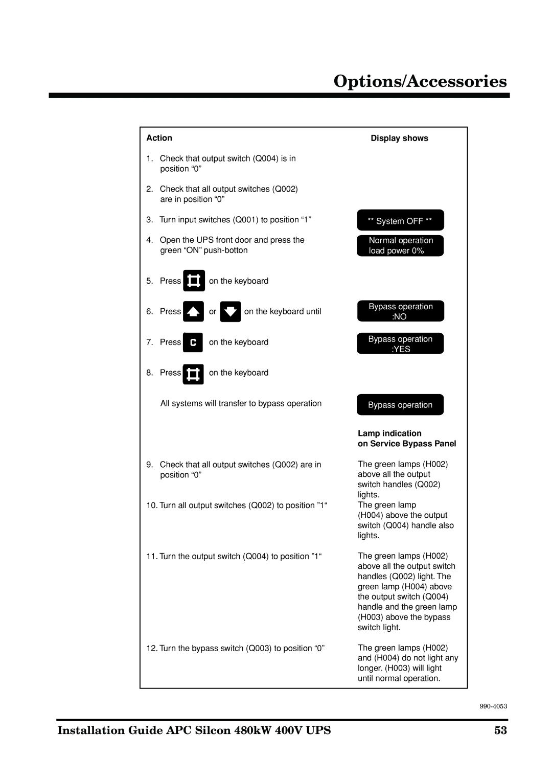
Action
1.Check that output switch (Q004) is in position “0”
2.Check that all output switches (Q002) are in position “0”
3.Turn input switches (Q001) to position “1”
4.Open the UPS front door and press the green “ON”
5.Press ![]()
![]() on the keyboard
on the keyboard
6.Press ![]() or
or ![]() on the keyboard until
on the keyboard until
7. | Press | on the keyboard |
8. | Press | on the keyboard |
All systems will transfer to bypass operation
9.Check that all output switches (Q002) are in position “0”
10.Turn all output switches (Q002) to position ”1“
11.Turn the output switch (Q004) to position ”1“
12. Turn the bypass switch (Q003) to position “0”
Display shows
** System OFF **
Normal operation load power 0%
Bypass operation :NO
Bypass operation
:YES
Bypass operation
Lamp indication
on Service Bypass Panel
The green lamps (H002) above all the output switch handles (Q002) lights.
The green lamp
(H004) above the output switch (Q004) handle also lights.
The green lamps (H002) above all the output switch handles (Q002) light. The green lamp (H004) above the output switch (Q004) handle and the green lamp (H003) above the bypass switch light.
The green lamps (H002) and (H004) do not light any longer. (H003) will light until normal operation.
Installation Guide APC Silcon 480kW 400V UPS | 53 |