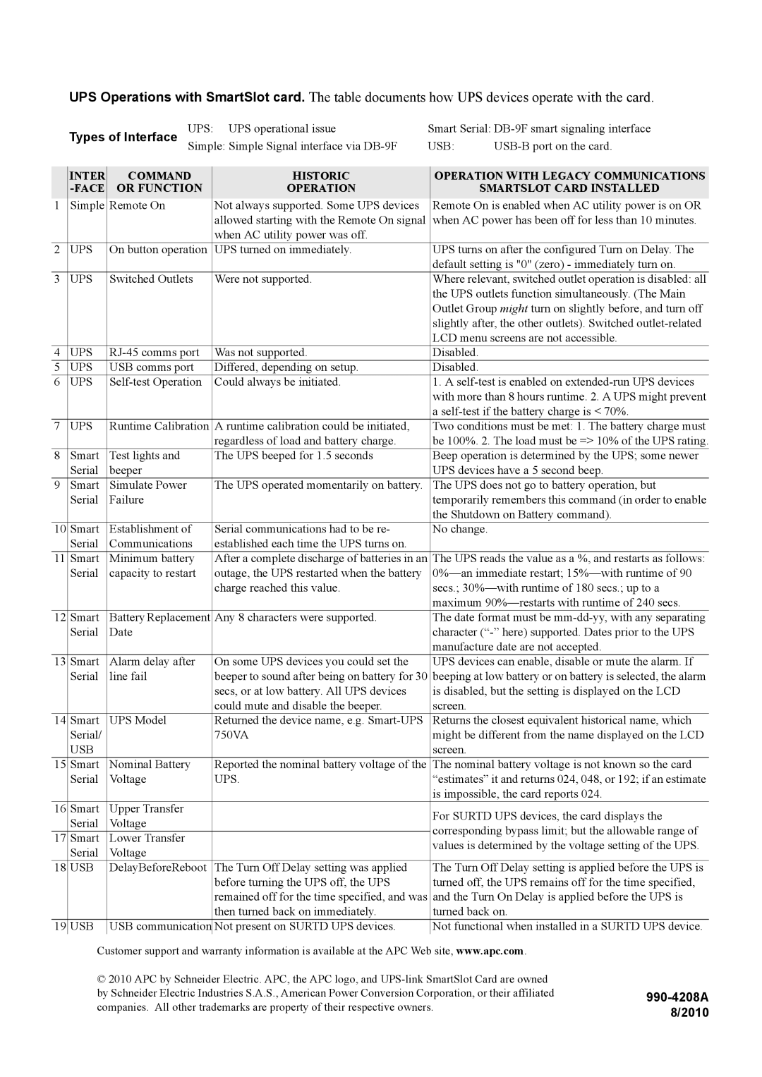
UPS Operations with SmartSlot card. The table documents how UPS devices operate with the card.
|
| UPS: | UPS operational issue | Smart Serial: | |||
| Types of Interface Simple: Simple Signal interface via | USB: | |||||
| INTER | COMMAND |
| HISTORIC | OPERATION WITH LEGACY COMMUNICATIONS |
| |
| OR FUNCTION |
| OPERATION |
| SMARTSLOT CARD INSTALLED |
| |
1 | Simple | Remote On |
| Not always supported. Some UPS devices | Remote On is enabled when AC utility power is on OR |
| |
|
|
|
| allowed starting with the Remote On signal | when AC power has been off for less than 10 minutes. | ||
|
|
|
| when AC utility power was off. |
|
|
|
2 | UPS | On button operation |
| UPS turned on immediately. | UPS turns on after the configured Turn on Delay. The |
| |
|
|
|
|
| default setting is "0" (zero) - immediately turn on. | ||
3 | UPS | Switched Outlets |
| Were not supported. | Where relevant, switched outlet operation is disabled: all |
| |
|
|
|
|
| the UPS outlets function simultaneously. (The Main | ||
|
|
|
|
| Outlet Group might turn on slightly before, and turn off | ||
|
|
|
|
| slightly after, the other outlets). Switched | ||
|
|
|
|
| LCD menu screens are not accessible. | ||
4 | UPS |
| Was not supported. | Disabled. |
|
| |
5 | UPS | USB comms port |
| Differed, depending on setup. | Disabled. |
|
|
6 | UPS |
| Could always be initiated. | 1. A |
| ||
|
|
|
|
| with more than 8 hours runtime. 2. A UPS might prevent | ||
|
|
|
|
| a | ||
7 | UPS | Runtime Calibration |
| A runtime calibration could be initiated, | Two conditions must be met: 1. The battery charge must |
| |
|
|
|
| regardless of load and battery charge. | be 100%. 2. The load must be => 10% of the UPS rating. | ||
8 | Smart | Test lights and |
| The UPS beeped for 1.5 seconds | Beep operation is determined by the UPS; some newer |
| |
| Serial | beeper |
|
| UPS devices have a 5 second beep. | ||
9 | Smart | Simulate Power |
| The UPS operated momentarily on battery. | The UPS does not go to battery operation, but |
| |
| Serial | Failure |
|
| temporarily remembers this command (in order to enable | ||
|
|
|
|
| the Shutdown on Battery command). | ||
10 | Smart | Establishment of |
| Serial communications had to be re- | No change. |
| |
| Serial | Communications |
| established each time the UPS turns on. |
|
|
|
11 | Smart | Minimum battery |
| After a complete discharge of batteries in an | The UPS reads the value as a %, and restarts as follows: |
| |
| Serial | capacity to restart |
| outage, the UPS restarted when the battery | |||
|
|
|
| charge reached this value. | secs.; | ||
|
|
|
|
| maximum | ||
12 | Smart | Battery Replacement | Any 8 characters were supported. | The date format must be |
| ||
| Serial | Date |
|
| character | ||
|
|
|
|
| manufacture date are not accepted. | ||
13 | Smart | Alarm delay after |
| On some UPS devices you could set the | UPS devices can enable, disable or mute the alarm. If |
| |
| Serial | line fail |
| beeper to sound after being on battery for 30 | beeping at low battery or on battery is selected, the alarm | ||
|
|
|
| secs, or at low battery. All UPS devices | is disabled, but the setting is displayed on the LCD | ||
|
|
|
| could mute and disable the beeper. | screen. |
|
|
14 | Smart | UPS Model |
| Returned the device name, e.g. | Returns the closest equivalent historical name, which |
| |
| Serial/ |
|
| 750VA | might be different from the name displayed on the LCD | ||
| USB |
|
|
| screen. |
|
|
15 | Smart | Nominal Battery |
| Reported the nominal battery voltage of the | The nominal battery voltage is not known so the card |
| |
| Serial | Voltage |
| UPS. | “estimates” it and returns 024, 048, or 192; if an estimate | ||
|
|
|
|
| is impossible, the card reports 024. |
| |
16 | Smart | Upper Transfer |
|
| For SURTD UPS devices, the card displays the | ||
| Serial | Voltage |
|
| |||
|
|
| corresponding bypass limit; but the allowable range of | ||||
17 | Smart | Lower Transfer |
|
| |||
|
| values is determined by the voltage setting of the UPS. | |||||
| Serial | Voltage |
|
| |||
|
|
|
|
|
| ||
18 | USB | DelayBeforeReboot |
| The Turn Off Delay setting was applied | The Turn Off Delay setting is applied before the UPS is |
| |
|
|
|
| before turning the UPS off, the UPS | turned off, the UPS remains off for the time specified, | ||
|
|
|
| remained off for the time specified, and was | and the Turn On Delay is applied before the UPS is | ||
|
|
|
| then turned back on immediately. | turned back on. | ||
19 | USB | USB communication | Not present on SURTD UPS devices. | Not functional when installed in a SURTD UPS device. |
| ||
Customer support and warranty information is available at the APC Web site, www.apc.com.
© 2010 APC by Schneider Electric. APC, the APC logo, and