NOTE: SETTINGS ARE MADE THROUGH SUPPLIED POWERCHUTE SOFTWARE OR OPTIONAL SMART SLOT
ACCESSORY CARDS.
FUNCTION |
| FACTORY | USER SELECTABLE CHOICES | DESCRIPTION | ||||
| DEFAULT | |||||||
|
|
|
|
|
|
| ||
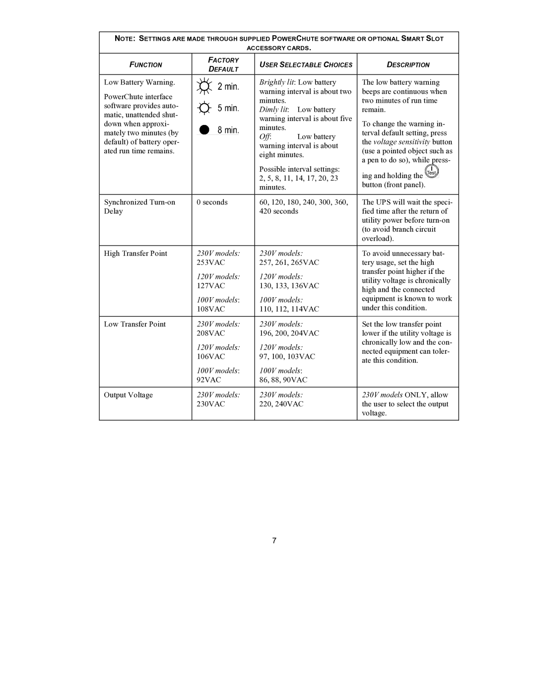
Low Battery Warning. |
|
|
| Brightly lit: Low battery | The low battery warning | |||
|
|
| ||||||
PowerChute interface |
|
|
| warning interval is about two | beeps are continuous when | |||
|
|
| minutes. |
| two minutes of run time | |||
software provides auto- |
|
|
|
| ||||
|
|
| Dimly lit: | Low battery | remain. | |||
matic, unattended shut- |
|
|
| |||||
|
|
| warning interval is about five |
|
|
| ||
down when approxi- |
|
|
| To change the warning in- | ||||
|
|
| minutes. |
| ||||
mately two minutes (by |
|
|
|
| terval default setting, press | |||
|
|
| Off: | Low battery | ||||
|
|
| ||||||
default) of battery oper- |
|
|
| the voltage sensitivity button | ||||
|
|
| warning interval is about | |||||
ated run time remains. |
|
|
| (use a pointed object such as | ||||
|
|
| eight minutes. | |||||
|
|
|
| a pen to do so), while press- | ||||
|
|
|
| Possible interval settings: | ||||
|
|
|
| ing and holding the |
|
| ||
|
|
|
| 2, 5, 8, 11, 14, 17, 20, 23 |
|
| ||
|
|
|
|
| ||||
|
|
|
| minutes. |
| button (front panel). | ||
|
|
|
| |||||
Synchronized | 0 seconds | 60, 120, 180, 240, 300, 360, | The UPS will wait the speci- | |||||
Delay |
|
|
| 420 seconds | fied time after the return of | |||
|
|
|
|
|
| utility power before | ||
|
|
|
|
|
| (to avoid branch circuit | ||
|
|
|
|
|
| overload). | ||
|
|
|
| |||||
High Transfer Point | 230V models: | 230V models: | To avoid unnecessary bat- | |||||
| 253VAC | 257, 261, 265VAC | tery usage, set the high | |||||
| 120V models: | 120V models: | transfer point higher if the | |||||
| utility voltage is chronically | |||||||
| 127VAC | 130, 133, 136VAC | ||||||
| high and the connected | |||||||
|
|
|
|
|
| |||
| 100V models: | 100V models: | equipment is known to work | |||||
| 108VAC | 110, 112, 114VAC | under this condition. | |||||
|
|
|
| |||||
Low Transfer Point | 230V models: | 230V models: | Set the low transfer point | |||||
| 208VAC | 196, 200, 204VAC | lower if the utility voltage is | |||||
| 120V models: | 120V models: | chronically low and the con- | |||||
| nected equipment can toler- | |||||||
| 106VAC | 97, 100, 103VAC | ||||||
| ate this condition. | |||||||
|
|
|
|
|
| |||
| 100V models: | 100V models: |
|
|
| |||
| 92VAC | 86, 88, 90VAC |
|
|
| |||
|
|
|
| |||||
Output Voltage | 230V models: | 230V models: | 230V models ONLY, allow | |||||
| 230VAC | 220, 240VAC | the user to select the output | |||||
|
|
|
|
|
| voltage. | ||
|
|
|
|
|
|
|
|
|
7