TROUBLESHOOTING | SPECIFICATIONS |
|
|

 SERVICE
If the
Problem | Possible Cause | Corrective Action |
|
|
|
Ensure the | ||
|
|
|
| Disconnect | |
|
| (push in) the rear panel circuit breaker. Switch on the |
|
| and plug in devices one at a time. If the circuit breaker trips |
|
| again, disconnect the device that caused the breaker to trip. |
|
|
|
| Utility input voltage quality is out of range. | Consider adjusting the transfer voltage and sensitivity. See |
|
| Transfer Voltage and Sensitivity Adjustment. |
|
|
|
| Internal battery cartridge is not connected. | Connect battery cartridge (see Connect Battery Cartridge). |
|
|
|
Equipment plugged into a Surge Only outlet. | Unplug device from 'Surge Only' outlet and move to a 'Battery | |
essential equipment during an |
| Backup' outlet. |
outage. |
|
|
|
|
|
Disconnect | ||
although utility power exists. |
| (push in) the rear panel circuit breaker. Switch the |
|
| and plug equipment in |
|
| again, disconnect the device that caused the breaker to trip. |
|
|
|
| Utility input voltage quality is out of range. | Consider adjusting the transfer voltage and sensitivity. See |
|
| Transfer Voltage and Sensitivity Adjustment. |
|
|
|
Unplug | ||
expected backup time. |
| the Battery Backup outlets and plug into 'Surge Only' outlets. |
|
|
|
| Charge the battery cartridge for 8 hours. | |
| recent power outage and has not had time to | reduced until the battery cartridge is fully charged. |
| recharge. |
|
|
|
|
| Battery has reached the end of its life. | Replace battery cartridge (see Order Replacement Battery |
|
| Cartridge). |
|
|
|
Red Replace Battery indicator is | Internal battery cartridge is not connected. | Connect battery cartridge (see Connect Battery Cartridge). |
flashing. Green On Line indicator |
|
|
is on. |
|
|
|
|
|
Red Replace Battery indicator is | Battery has reached the end of its life. | Replace the battery cartridge (see Order Replacement Battery |
on. |
| Cartridge). |
|
|
|
Red Overload indicator is on or | Connected equipment is drawing more power than | Move one or more equipment power plugs from Battery Backup |
flashing. | the | outlets to Surge Only outlets. |
|
|
|
Green On Line indicator is on and | Internal UPS fault. | Contact APC Technical Support (see Contact Information). |
all other front panel indicators are |
|
|
flashing. |
|
|
|
|
|
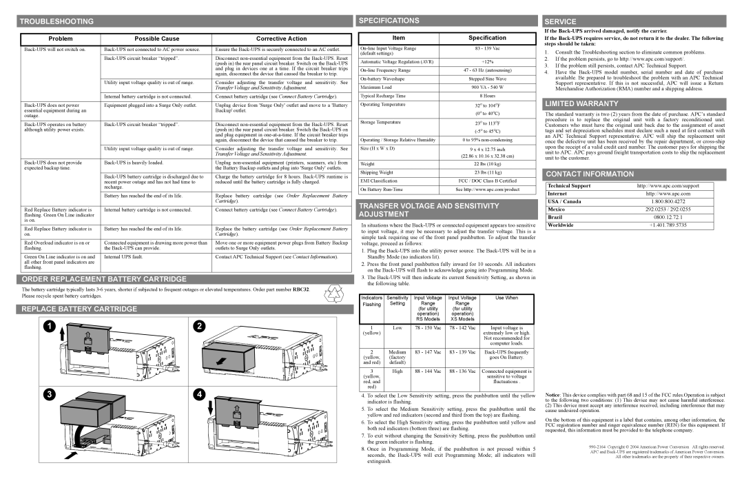
ORDER REPLACEMENT BATTERY CARTRIDGE
The battery cartridge typically lasts
REPLACE BATTERY CARTRIDGE
1 | 2 |
3 | 4 |
Item | Specification |
|
|
83 - 139 Vac | |
(default settings) |
|
|
|
Automatic Voltage Regulation (AVR) | +12% |
|
|
47 - 63 Hz (autosensing) | |
|
|
Stepped Sine Wave | |
|
|
Maximum Load | 900 VA - 540 W |
|
|
Typical Recharge Time | 8 Hours |
|
|
Operating Temperature | 32o to 104oF |
| (0o to 40oC) |
Storage Temperature | 23o to 113oF |
| |
Operating / Storage Relative Humidity | 0 to 95% |
|
|
Size (H x W x D) | 9 x 4 x 12.75 inch |
| (22.86 x 10.16 x 32.38 cm) |
|
|
Weight | 22 lbs (10 kg) |
|
|
Shipping Weight | 23 lbs (11 kg) |
|
|
EMI Classification | FCC / DOC Class B Certified |
|
|
On Battery | See http://www.apc.com/product |
|
|
TRANSFER VOLTAGE AND SENSITIVITY ADJUSTMENT
In situations where the
1.Plug the
2.Press the front panel pushbutton fully inward for 10 seconds. All indicators on the
3.The
Indicators | Sensitivity | Input Voltage | Input Voltage | Use When |
Flashing | Setting | Range | Range |
|
|
| (for utility | (for utility |
|
|
| operation) | operation) |
|
|
| RS Models | XS Models |
|
|
|
|
|
|
1 | Low | 78 - 150 Vac | 78 - 142 Vac | Input voltage is |
(yellow) |
|
|
| extremely low or high. |
|
|
|
| Not recommended for |
|
|
|
| computer loads. |
|
|
|
|
|
2 | Medium | 83 - 147 Vac | 83 - 139 Vac | |
(yellow, | (factory |
|
| goes On Battery. |
and red) | default) |
|
|
|
|
|
|
|
|
3 | High | 88 - 144 Vac | 88 - 136 Vac | Connected equipment is |
(yellow, |
|
|
| sensitive to voltage |
red, and |
|
|
| fluctuations . |
red) |
|
|
|
|
|
|
|
|
|
4.To select the Low Sensitivity setting, press the pushbutton until the yellow indicator is flashing.
5.To select the Medium Sensitivity setting, press the pushbutton until the yellow and red indicators (second and third from the top) are flashing.
6.To select the High Sensitivity setting, press the pushbutton until yellow and both red indicators (bottom three) are flashing.
7.To exit without changing the Sensitivity Setting, press the pushbutton until the green indicator is flashing.
8.Once in Programming Mode, if the pushbutton is not pressed within 5 seconds, the
If the
1.Consult the Troubleshooting section to eliminate common problems.
2.If the problem persists, go to http://www.apc.com/support/.
3.If the problem still persists, contact APC Technical Support.
4.Have the
LIMITED WARRANTY
The standard warranty is two (2) years from the date of purchase. APC’s standard procedure is to replace the original unit with a factory reconditioned unit. Customers who must have the original unit back due to the assignment of asset tags and set depreciation schedules must declare such a need at first contact with an APC Technical Support representative. APC will ship the replacement unit once the defective unit has been received by the repair department, or
CONTACT INFORMATION
Technical Support | http://www.apc.com/support |
Internet | http://www.apc.com |
USA / Canada | 1.800.800.4272 |
Mexico | 292.0253 / 292.0255 |
Brazil | 0800.12.72.1 |
Worldwide | +1.401.789.5735 |
Notice: This device complies with part 68 and 15 of the FCC rules.Operation is subject
to the following two conditions: (1) This device may not cause harmful interference.
(2)This device must accept any interference received, including interference that may cause undesired operation.
On the bottom of this equipment is a label that contains, among other information, the FCC registration number and ringer equivalence number (REN) for this equipment. If requested, this information must be provided to the telephone company.
All other trademarks are the property of their respective owners.