MAKE ELECTRICAL CONNECTIONS
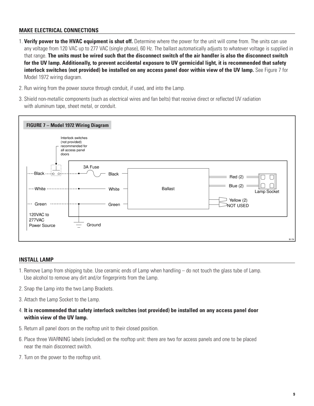
1.Verify power to the HVAC equipment is shut off. Determine where the power for the unit will come from. The units can use any voltage from 120 VAC up to 277 VAC (single phase), 60 Hz. The ballast automatically adjusts to whatever voltage is supplied in that range. The units must be wired such that the disconnect switch of the air handler is also the disconnect switch for the UV lamp. Additionally, to prevent accidental exposure to UV germicidal light, it is recommended that safety interlock switches (not provided) be installed on any access panel door within view of the UV lamp. See Figure 7 for Model 1972 wiring diagram.
2.Run wiring from the power source through conduit, if used, and into the Lamp.
3.Shield
FIGURE 7 – Model 1972 Wiring Diagram |
| |
| Interlock switches |
|
| (not provided) |
|
| recommended for |
|
| all access panel |
|
| doors |
|
| 3A Fuse |
|
Black | Black | Red (2) |
|
| |
White | White | Blue (2) |
Ballast | ||
|
| Lamp Socket |
Green | Green | Yellow (2) |
NOT USED | ||
120VAC to |
|
|
277VAC | Ground |
|
Power Source |
| |
|
| |
INSTALL LAMP
1.Remove Lamp from shipping tube. Use ceramic ends of Lamp when handling – do not touch the glass tube of Lamp. Use alcohol to remove any dirt and/or fingerprints from the Lamp.
2.Snap the Lamp into the two Lamp Brackets.
3.Attach the Lamp Socket to the Lamp.
4.It is recommended that safety interlock switches (not provided) be installed on any access panel door within view of the UV lamp.
5.Return all panel doors on the rooftop unit to their closed position.
6.Place three WARNING labels (included) on the rooftop unit: there are two for access panels and one to be placed near the main disconnect switch.
7.Turn on the power to the rooftop unit.
9